Magnetically driven air moving apparatus, with magnetically tipped fan blades and a single field coil and core

a technology of magnetically tipped fan blades and moving apparatuses, which is applied in the direction of positive displacement liquid engine, piston pump, magnetic circuit shape/form/construction, etc., can solve the problems of affecting the reliability of the motor used in the fan assembly, the noise of the fan becoming significantly loud and undesirable, and the type of fan assembly being susceptible to a variety of failures

Inactive Publication Date: 2005-05-24
MOTOROLA MOBILITY LLC
View PDF13 Cites 18 Cited by
  • Summary
  • Abstract
  • Description
  • Claims
  • Application Information

AI Technical Summary

Benefits of technology

[0011]In each embodiment described above, the fan housing includes a field coil, which is integrated into the fan housing. The core of the field is constructed of a flexible laminate that allows it to be placed around the circumference of the housing after the windings have been attached. A particular advantage of the present embodiment is that only a single coil is needed, rather than two or more, for operating the magnetic fan. Additional coils may be added, but are not necessary, thereby reducing the cost and weight of the fan.

Problems solved by technology

As such, fan noise becomes significantly loud and undesirable.
These types of fan assemblies are susceptible to a variety of failures.
For example, the reliability of the motor used in the fan assembly may be compromised due to the heat generated by the motor or the heat of the surroundings in which the motor operates.
Similarly, the heat affecting the motor also may affect the life of the fan bearings, resulting in premature failure of the fan.
Another disadvantage of existing fan assemblies is the noise generated by these devices.
Generally such increased cooling comes at cost in the form of increased noise.
Or, higher rotational speeds may be required, resulting in noisier motors.
Alternatively, multiple fans may be used, which also results in increased noise due to the multiple motors in operation.

Method used


Image

  • Magnetically driven air moving apparatus, with magnetically tipped fan blades and a single field coil and core
  • Magnetically driven air moving apparatus, with magnetically tipped fan blades and a single field coil and core
  • Magnetically driven air moving apparatus, with magnetically tipped fan blades and a single field coil and core

Examples


Embodiment Construction

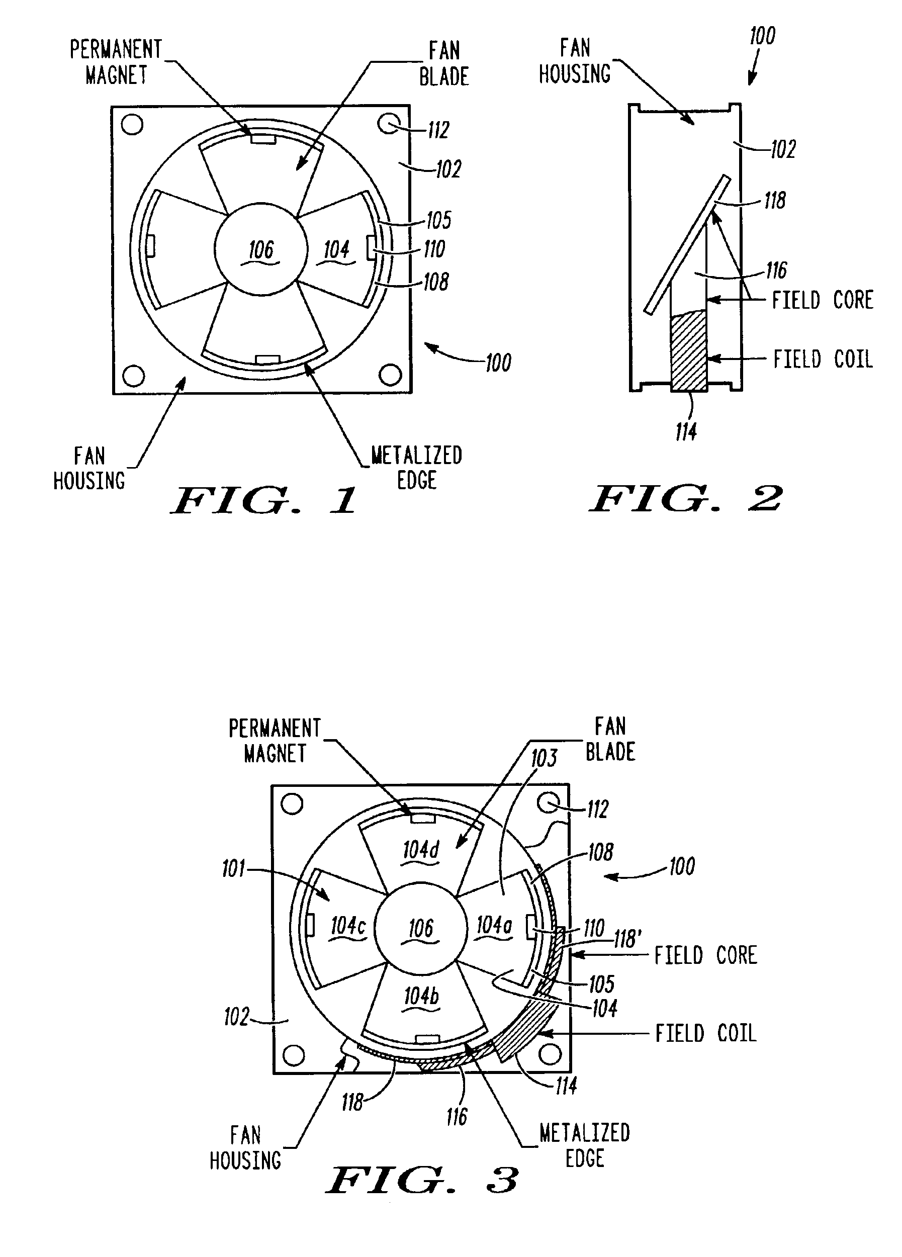
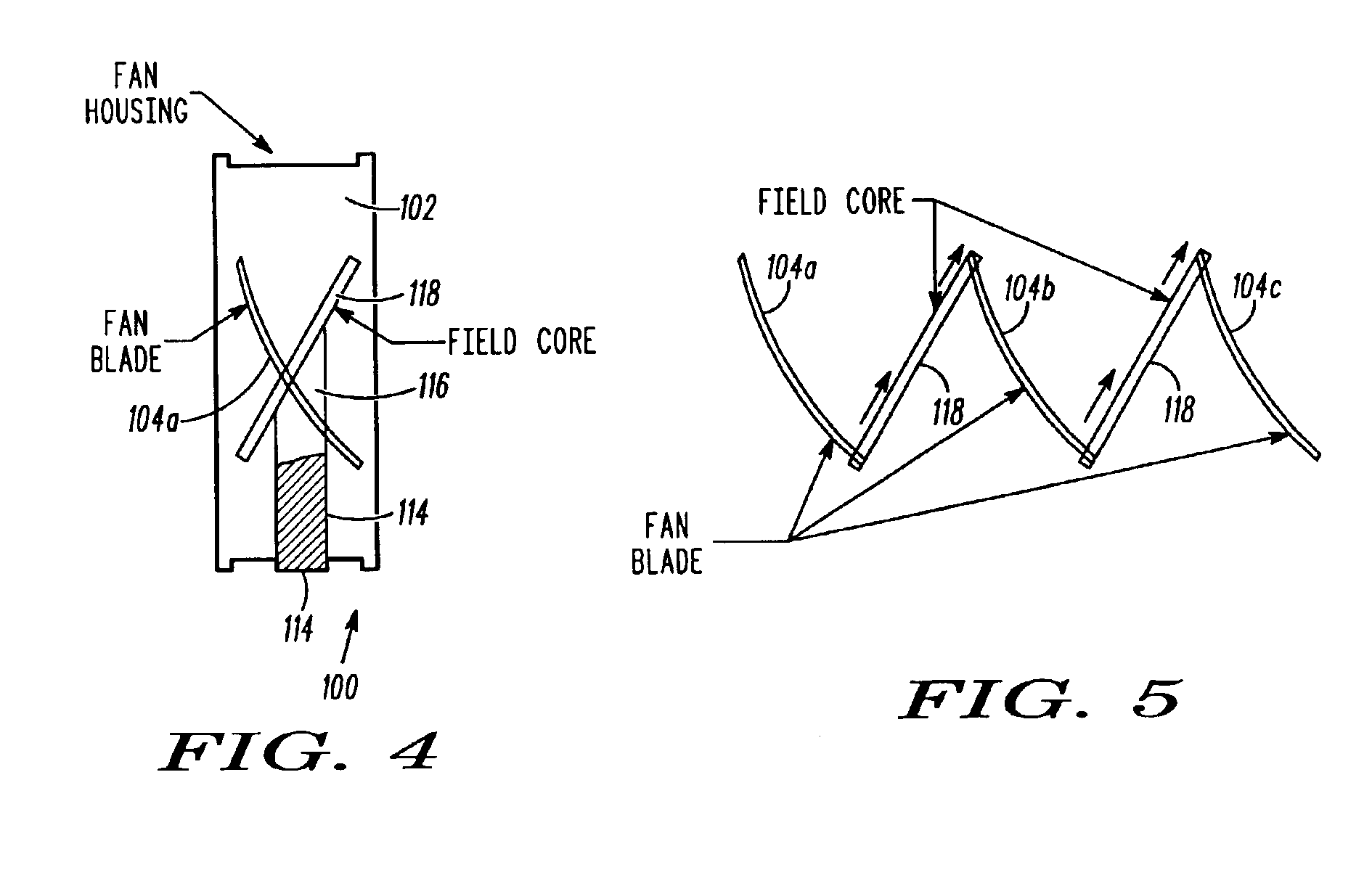
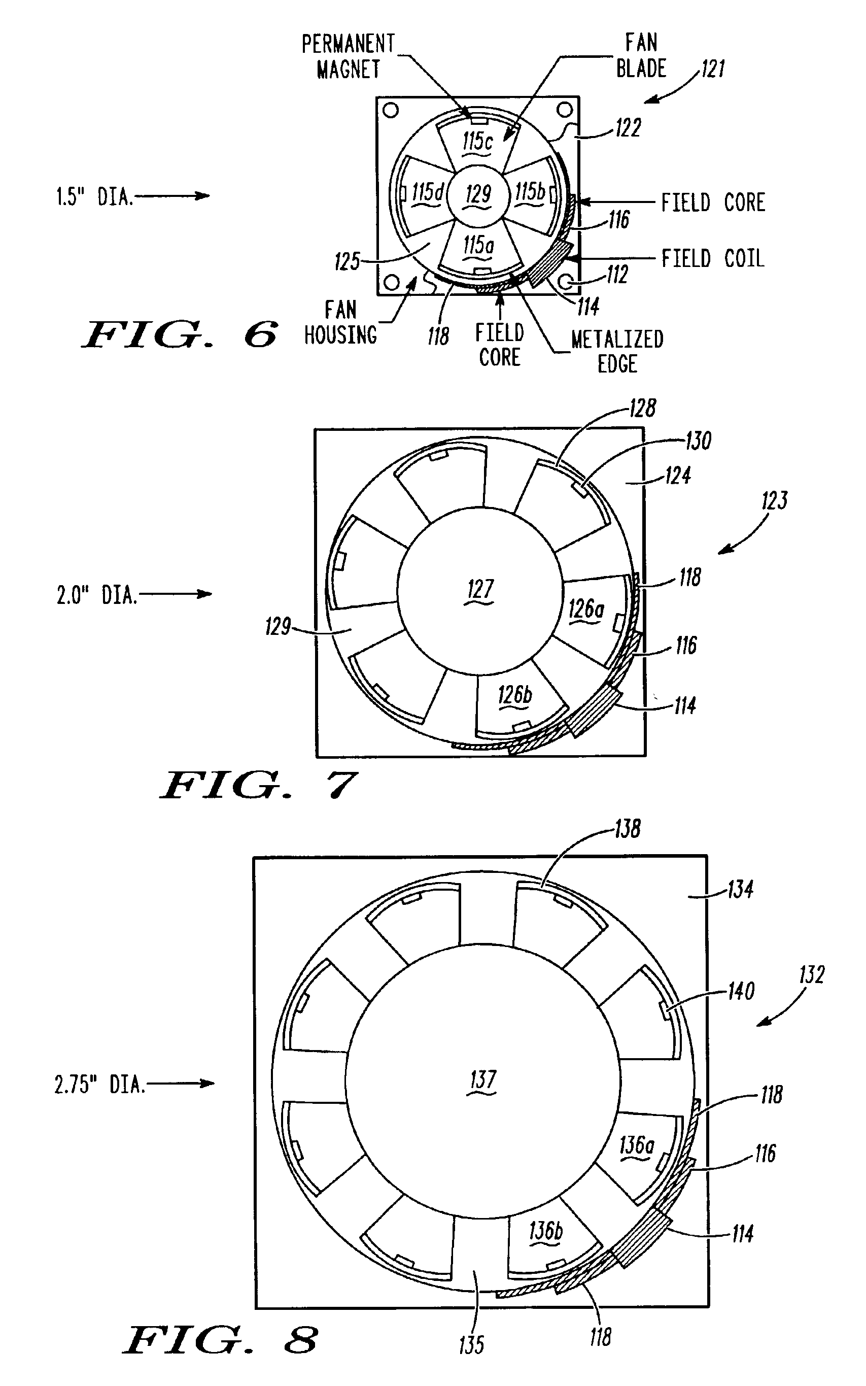
[0010]The present invention is directed to an improved air moving device, such as a fan, that is scalable for use in a variety of applications requiring different fan sizes. In a first embodiment, the fan includes a number of fan blades, each having a discrete magnet mounted thereon. The orientation of each magnet is such that the direction of the magnetic field alternates from one blade to the next. Furthermore, the outside edge of each blade is metalized in a way that the magnetic field is present across the entire outer edge of the fan blade. In another embodiment, the fan blade assembly includes fan blades fabricated of a ferrous material in which the tips of the blades are magnetized through exposure to a strong magnetic field after fabrication of the blade assembly. Advantageously, in both embodiments, the configuration of the blades is such that that the differential in field strength assists with the rotation of the fan blades.

[0011]In each embodiment described above, the fa...


PUM


Abstract

An improved air moving device that is scalable for use in a variety of applications requiring different fan sizes. The fan includes a number of fan blades, each having a discrete magnet mounted thereon. The orientation of each magnet is such that the direction of the magnetic field alternates from one blade to the next. The outside edge of each blade is metalized in a way that the magnetic field is present across the entire outer edge of the fan blade. In an alternate embodiment the fan blade assembly includes fan blades fabricated of a ferrous material in which the tips of the blades are magnetized through exposure to a strong magnetic field after fabrication of the blade assembly. The configuration of the blades in both embodiments enables the differential in field strength to assist with the rotation of the fan blades.

Description

FIELD OF THE INVENTION[0001]The present invention relates generally to an air moving apparatus and, more particularly, to a fan for cooling electronic equipment with improved reliability and increased scalability.BACKGROUND OF THE INVENTION[0002]A wide variety of equipment and systems, such as portable and desktop computers, mainframe computers, communication infrastructure frames, automotive equipment, etc., include heat-generating components in their casings. As increasingly dense and higher performance electronics are packaged into smaller housings, the need for effective cooling systems is paramount to prevent failure of such sensitive electronics devices. One method used to remove heat from such equipment is to have an axial fan draw air from the exterior, of the casing to blow cooling air over the heat-generating components. However, as the number of electronics devices in offices and households increases, so too does the number of cooling fans. As such, fan noise becomes sign...

Claims


Application Information

Patent Timeline
Patent Type & Authority Patents(United States)
IPC IPC(8): F04D25/06F04D25/02
CPCF04D25/066
Inventor MASTERTON, PATRICK
Owner MOTOROLA MOBILITY LLC
Why Eureka
Try Eureka