Display device

a display device and display technology, applied in the field of display devices, can solve the problems of complex structure, display devices may not be used in a certain type of vehicles, and may not be optimally raised and lowered, so as to achieve the effect of reducing the entire depth dimension of the display device, easy assembly and convenient manufacturing

Active Publication Date: 2016-10-04
ALPINE ELECTRONICS INC
View PDF12 Cites 2 Cited by
  • Summary
  • Abstract
  • Description
  • Claims
  • Application Information

AI Technical Summary

Benefits of technology

[0008]It is an object of the present disclosure to provide a display device which performs a tilt adjustment regardless of the raised and lowered position of the monitor while reducing the depth dimension of the display device.
[0010]In the display device having the above configuration, when the raising and lowering gear that meshes with the rack rotates in either the forward or reverse direction by the first drive mechanism, rotation of the raising and lowering gear is converted into a linear motion of the monitor via a mesh portion of the rack. Accordingly, the guided member moves in the up and down direction while being guided by the guide member, and the raised and lowered position of the monitor can be adjusted. Further, when the guide member that engages with the guided member rotates by the second drive mechanism, the monitor pivots about the shaft by rotation of the guide member, and the tilt angle of the monitor can be adjusted. Since one of the raising and lowering gear and the guide member is rotatably supported by the shaft and the other is unrotatably supported by the shaft, the guide member does not rotate during the raising and lowering operation of the monitor performed by rotation of the raising and lowering gear, and the raising and lowering gear does not rotate during tilt adjustment of the monitor performed by rotation of the guide member. Accordingly, the tilt adjustment can be performed regardless of the height position of the monitor. In addition, since the rotation center of the raising and lowering gear and the pivot center of the guide member are coaxially located, the entire depth dimension of the display device can be reduced.
[0013]Further, in the above configuration, it is preferable that the rack is disposed at a center portion on the back face of the monitor and a pair of the guided members is disposed on both sides of the rack on the back face of the monitor, and a pair of guide members is supported on both ends of the shaft so as to correspond to the guided members. According to this configuration, the raising and lowering operation and the tilt operation of the monitor can be smoothly performed in a balanced manner.
[0014]Further, in the above configuration, it is preferable that the shaft has a holding section having a circular cross section and a stepped down portion having a non-circular cross section, and one of the raising and lowering gear and the guide member is rotatably supported by the holding section and the other is unrotatably engaged with the stepped down portion. According to this configuration, the shaft having the holding section and the stepped down portion can be easily manufactured by chamfering both ends of the round rod made of metal in a D shape or a double D shape, and the raising and lowering gear and the guide member can be easily assembled to the shaft.
[0015]According to the display device of the present disclosure, one of the raising and lowering gear and the guide member is rotatably supported by the shaft, while the other is unrotatably supported by the shaft. The guide member does not rotate during the raising and lowering operation of the monitor performed by rotation of the raising and lowering gear, while the raising and lowering gear does not rotate during tilt adjustment of the monitor performed by rotation of the guide member. Accordingly, the tilt adjustment can be performed regardless of the height position of the monitor, and in addition to that, since the rotation center of the raising and lowering gear and the pivot center of the guide member are coaxially located, the entire depth dimension of the display device can be reduced.

Problems solved by technology

As a result, the height position in which the tilt angle of the monitor is adjusted is limited to one location, and this may cause a problem that a tilt adjustment may not be performed at an optimal raised and lowered position desired by a user.
Further, in order to perform tilt adjustment of the monitor, it is necessary to provide a third guide hole on the bracket and a third shaft on the base to be guided by the third guide hole, which leads to a complicated structure.
In addition, since the positions of the first to third guide holes and the first to third shafts need to be offset in the front and back direction, the entire depth dimension of the display device becomes large, which causes a problem that the display device may not be used in a certain type of vehicle which does not have a sufficient space for installation.

Method used


Image

  • Display device
  • Display device
  • Display device

Examples


first embodiment

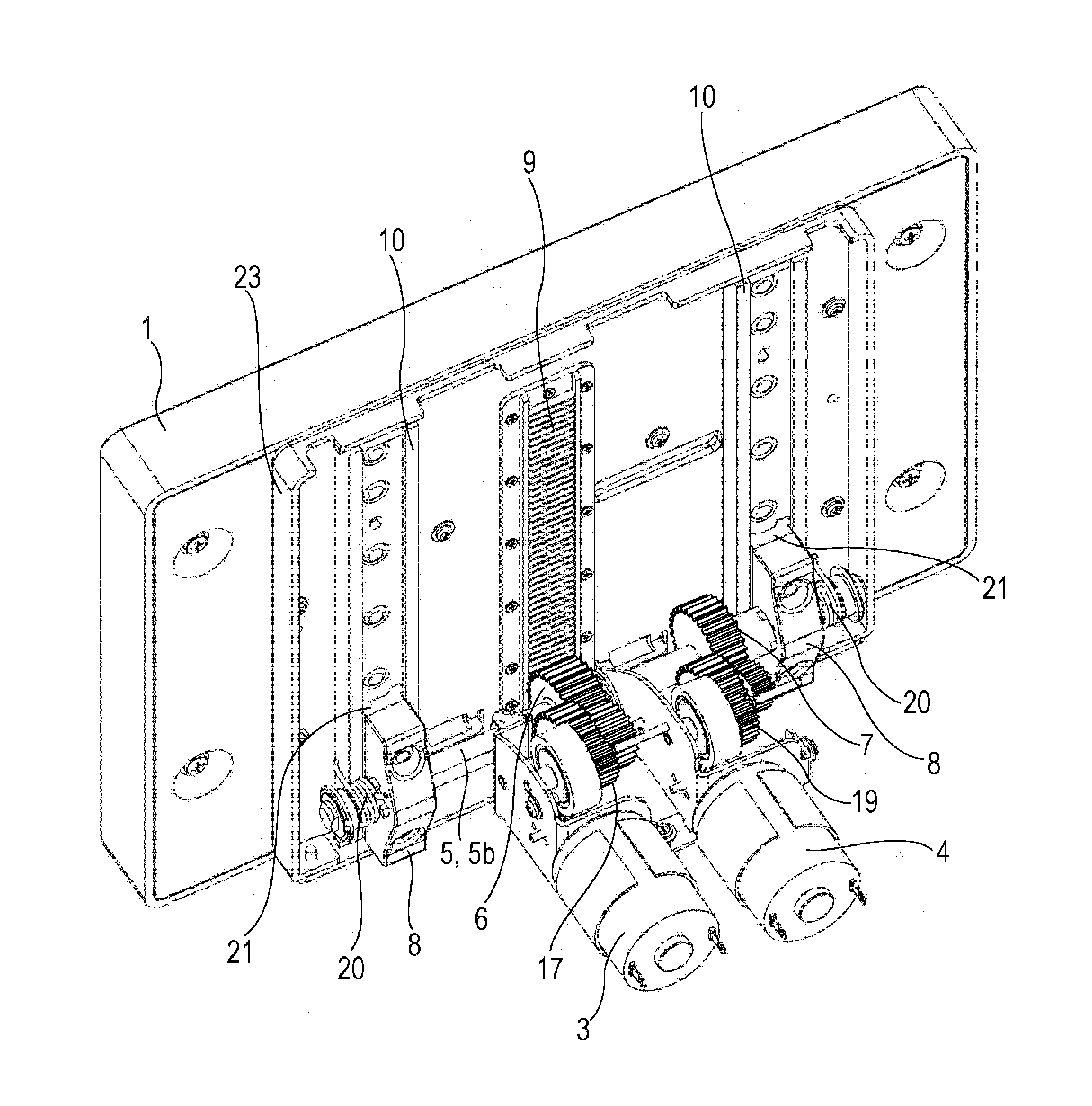
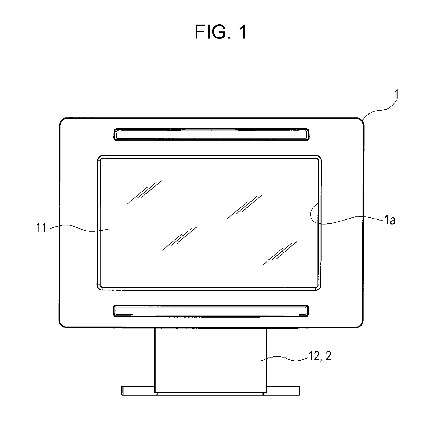
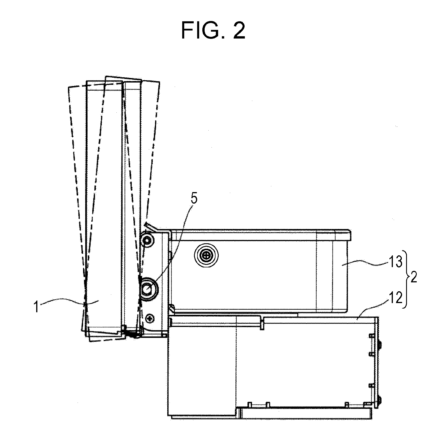
[0029]Embodiments of the invention will be described with reference to the drawings. As shown in FIGS. 1 to 11, a display device according to the invention mainly includes a monitor 1 formed in a cuboid shape, a base 2 that supports the monitor 1 while allowing raising and lowering and tilting of the monitor 1, first and second motors 3, 4 mounted on the base 2, a shaft 5 which is rotatably supported by the base 2, a raising and lowering gear 6 and a pivot gear 7 and a pair of guide members 8 inserted over the shaft 5, a rack 9 and a pair of guide rails 10 disposed on the back face of the monitor 1. A display panel 11 formed of an LCD or the like is housed in the monitor 1, and the display panel 11 is exposed through a rectangular opening la formed on the front face of the monitor 1.

[0030]The base 2 is composed of a lower housing 12 which houses circuit components, which are not shown in the figure, and an upper housing 13 disposed on the top surface of the lower housing 12 with the...

second embodiment

[0048]In the display device having the above configuration the raising and lowering gear 6 is unrotatably supported by the shaft 5, while the pivot gear 7 and the guide members 8 are rotatably supported by the shaft 5. Accordingly, when the raising and lowering gear 6 rotates by a drive source of the first motor 3, the raising and lowering gear 6 integrally rotates with the shaft 5, while the pivot gear 7 and the guide members 8 idly rotate about the shaft 5 and do not rotate. Further, when the pivot gear 7 rotates by a drive source of the second motor 4, the pivot gear 7 and the guide members 8 integrally rotate about the shaft 5 as a pivot point, while the raising and lowering gear 6 and the shaft 5 do not rotate.

[0049]Accordingly, similar to the above described first embodiment, the monitor 1 can be held at any height position between the uppermost position and the lowermost position by adjusting the rotation direction and the rotation amount of the first motor 3. In addition, t...


PUM


Abstract

A shaft is rotatably supported by an upper housing (base), a raising and lowering gear for a monitor is rotatably supported by the shaft, and a pivot gear and a guide member are unrotatably supported by the shaft. A rack and a guide rail are disposed on the back face of the monitor such that the raising and lowering gear meshes the rack and the guide member slidably engages with the guide rail. When the raising and lowering gear rotates by a drive source of a first motor, the guide rail is guided by the guide member to move upward and downward, and accordingly, the height position of the monitor is adjusted. When the pivot gear rotates by a drive source of a second motor, the guide member rotates along with the shaft, and accordingly, the tilt angle of the monitor is adjusted.

Description

RELATED APPLICATION[0001]The present application claims priority to Japanese Patent Application Number 2013-244154, filed Nov. 26, 2013, the entirety of which is hereby incorporated by reference.BACKGROUND[0002]1. Field of the Invention[0003]The present invention relates to display devices having a function of adjusting a height position and a tilt angle of a monitor.[0004]2. Description of the Related Art[0005]Display devices for vehicles are commonly used which include a raising and lowering mechanism for moving a monitor to a use position and a tilt mechanism for adjusting a tilt angle of a monitor, and the raising and lowering mechanism and the tilt mechanism are operated by a motor as a drive source. As a conventional example of such display devices, Japanese Unexamined Patent Application Publication No. 2010-12880 discloses a display device which includes first and second guide holes on a base which is disposed on the back face of a monitor and first and second shafts that eng...

Claims


Application Information

Patent Timeline
Patent Type & Authority Patents(United States)
IPC IPC(8): G06F1/16F16M11/00B60K35/00
CPCG06F1/1601B60K35/00F16M11/00B60K37/04B60K2370/67F16M11/046F16M11/18F16M11/2064
Inventor KATSUNUMA, HIDETO
Owner ALPINE ELECTRONICS INC
Why Eureka
Try Eureka