Electrical box with movable mounting system

a technology of mounting system and electrical box, which is applied in the direction of electrical apparatus casing/cabinet/drawer, installation of lighting conductors, coupling device connections, etc., can solve the problem of time-consuming repositioning process, achieve the effect of facilitating repositioning of electrical boxes, minimizing complexity and cost, and maximizing ease of repositioning electrical boxes

Active Publication Date: 2010-12-21
ALLIED MOLDED PRODS
View PDF18 Cites 19 Cited by
  • Summary
  • Abstract
  • Description
  • Claims
  • Application Information

AI Technical Summary

Benefits of technology

[0006]In concordance and agreement with the present invention, an electrical box including a mounting system which facilitates a repositioning of the electrical box, wherein a complexity and cost thereof are minimized, and an ease of repositioning the electrical box is maximized, has surprisingly been discovered.

Problems solved by technology

Further, the repositioning process can be time consuming.

Method used


Image

  • Electrical box with movable mounting system
  • Electrical box with movable mounting system
  • Electrical box with movable mounting system

Examples


Embodiment Construction

[0025]The following detailed description and appended drawings describe and illustrate various exemplary embodiments of the invention. The description and drawings serve to enable one skilled in the art to make and use the invention, and are not intended to limit the scope of the invention in any manner.

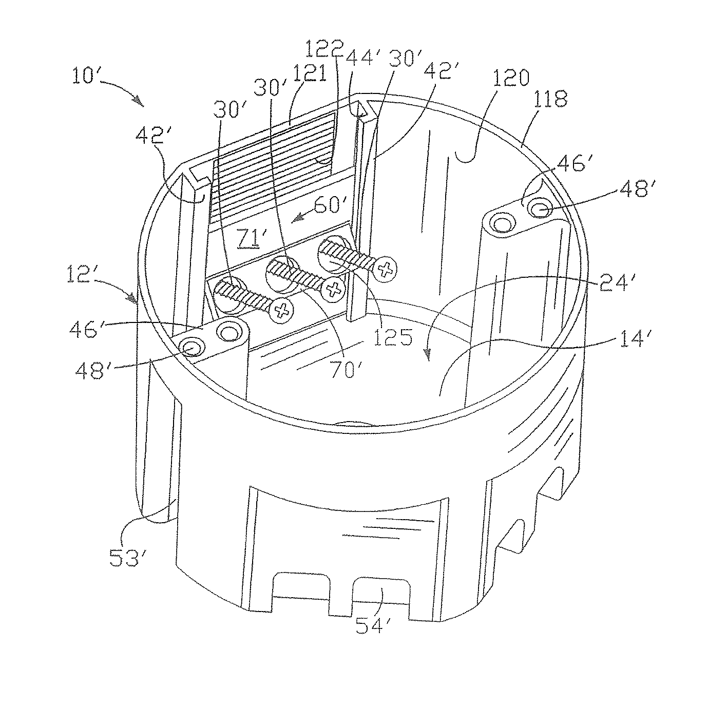
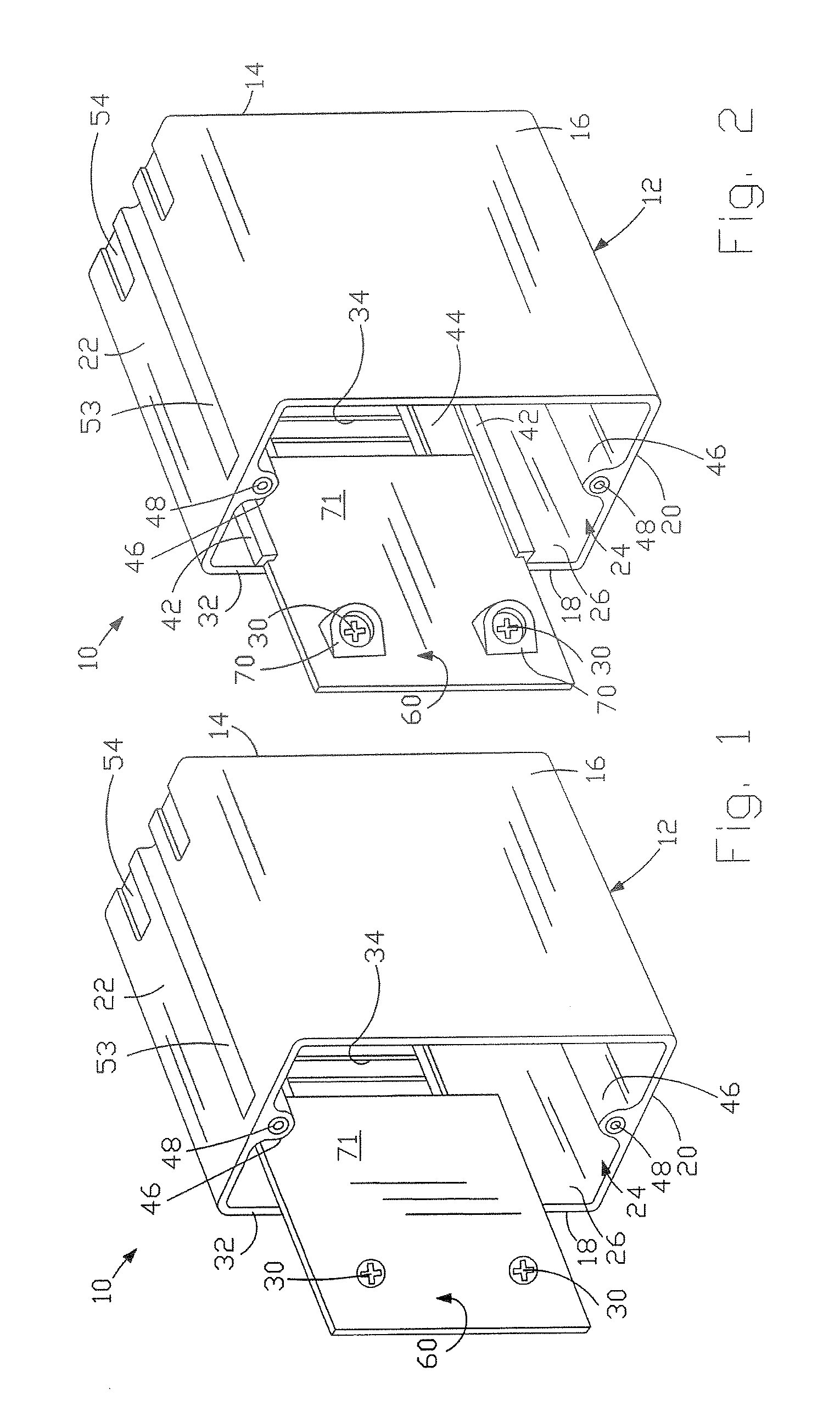
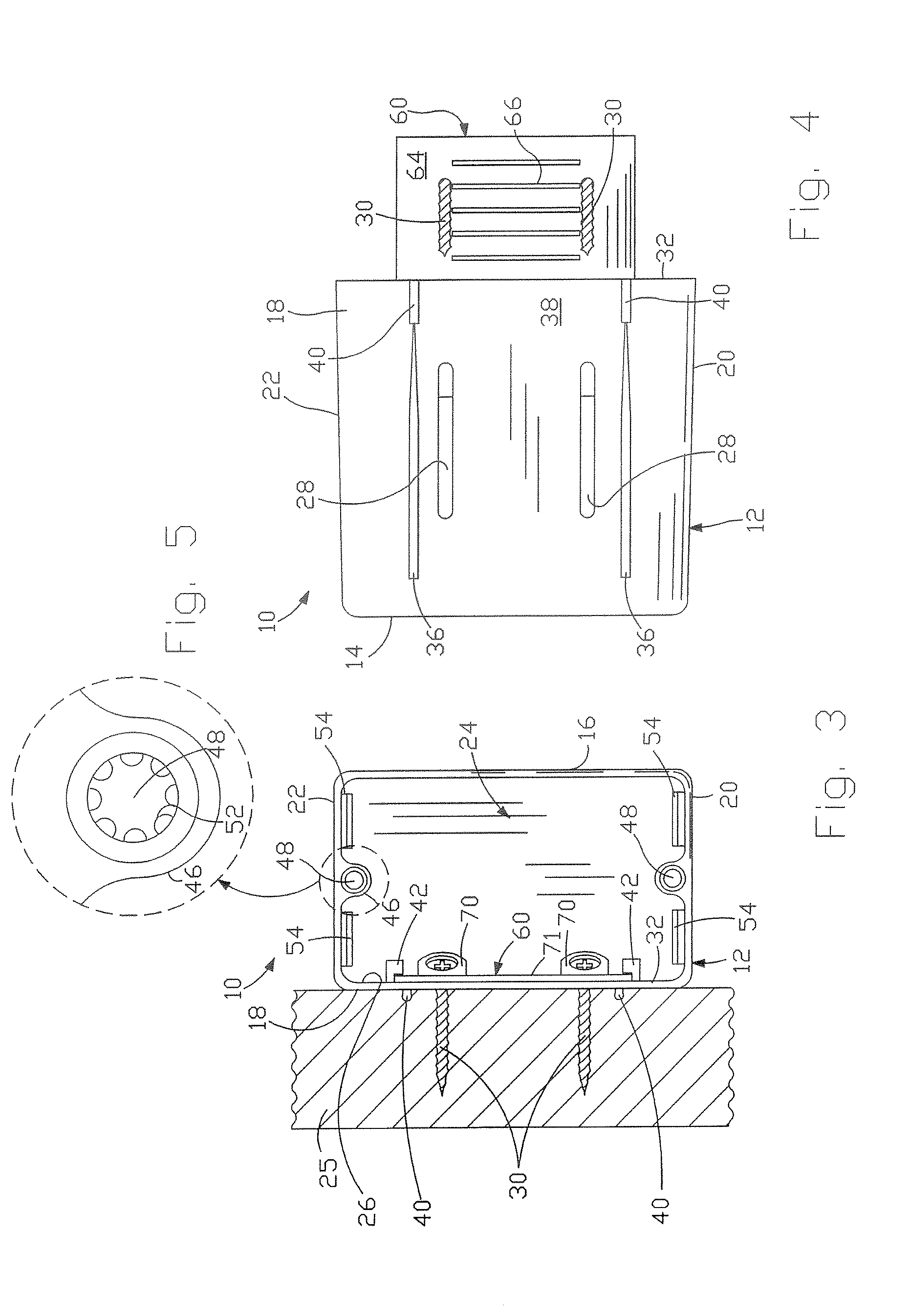
[0026]FIGS. 1 to 7 illustrate an electrical box 10 according to an embodiment of the invention. The electrical box 10 includes a hollow main body 12. Although the main body 12 shown has a generally rectangular shape, it is understood that the main body 12 can have any shape and size as desired. In the embodiment shown, the main body 12 includes a rear wall 14, a first sidewall 16, a second sidewall 18, a third sidewall 20, a fourth sidewall 22, and at least one open side defining a cavity 24 therein. It is understood that the main body 12 can include additional or fewer sidewalls as desired. The cavity 24 is adapted to receive electrical wiring, a receptacle, and the like, for exampl...


PUM


Abstract

An electrical box is disclosed, wherein the electrical box includes a mounting system that facilitates a repositioning of the electrical box on a mounting structure without a complete removal of fastening devices from the mounting structure.

Description

CROSS-REFERENCE TO RELATED APPLICATION[0001]This application claims the benefit of U.S. Provisional Patent Application Ser. No. 60 / 952,364 filed Jul. 27, 2007.FIELD OF THE INVENTION[0002]The present invention relates to an electrical box and more particularly to an electrical box having a movable mounting system that facilitates a repositioning of the electrical box.BACKGROUND OF THE INVENTION[0003]Typically, an electrical box is used to support and contain electrical devices and wiring in a centralized space. The electrical box protects the wiring and electrical devices contained therein from extrinsic conditions such rain, snow, and fire, for example. A cover plate can be provided to further protect the wiring and electrical devices and militate against accidental electrocution of a user. The electrical box is typically connected to a joist or other structural component of a building.[0004]Prior art electrical boxes include mounting systems with fastening devices that facilitate a...

Claims


Application Information

Patent Timeline
Patent Type & Authority Patents(United States)
IPC IPC(8): H02G3/08
CPCH02G3/081H02G3/10Y10S248/906
Inventor TRODER, WALTER P.
Owner ALLIED MOLDED PRODS
Why Eureka
Try Eureka