Splitboard bindings

a technology of splitboards and bindings, applied in the field of splitboards, can solve the problems of increasing weight, instability, and decreasing the torsional stiffness (or spring constant) of the boot bindings, and achieve the effects of eliminating weight and height, increasing weight, and instability

Active Publication Date: 2010-11-02
SPARK R&D IP HLDG LLC
View PDF20 Cites 47 Cited by
  • Summary
  • Abstract
  • Description
  • Claims
  • Application Information

AI Technical Summary

Benefits of technology

[0028]The most relevant teachings of the prior art focus on a boot binding with one or more adaptor mounting plates—so that boots and boot bindings designed for snowboarding can be adapted for use with splitboards. This approach is problematic, adding weight, instability, and decreasing the torsional stiffness (or spring constant) of the boot bindings. No solution has been offered in the prior art that eliminates the weight and height of the essentially ubiquitous “adaptor mounting plate” and, as recognized here, supplies the right amount of stiffness in the boot binding on the ankle to optimize rider control, while remaining comfortable and responsive for the soft boot rider.
[0029]Any solution must also allow the rider to easily reposition the boots when switching from snowboard riding to ski touring configuration, and the performance in ski touring configuration must also be improved.
[0030]I teach here that the prior art adaptor mounting plate, which serves the function of adapting both snowboard-type soft-boot bindings and hard boot bindings to the snowboard mounting blocks and also to the ski touring mounting brackets of the prior art, can be advantageously eliminated. The adaptor mounting plate, which is an essential component disclosed in single-embodiment patents such as U.S. Pat. Nos. 5,984,324 and 6,523,851, can be replaced with a box girder, in which the box girder is integral to the boot binding lower. I have obtained stiffer torsional spring constants in the boot bindings through this method of construction. While not being bound by theory, this teaching is a new solution to the problem of boot binding structural mechanics, and is shown to have unexpected advantages that improve the snowboard ride.

Problems solved by technology

This approach is problematic, adding weight, instability, and decreasing the torsional stiffness (or spring constant) of the boot bindings.

Method used


Image

  • Splitboard bindings
  • Splitboard bindings
  • Splitboard bindings

Examples


example 1

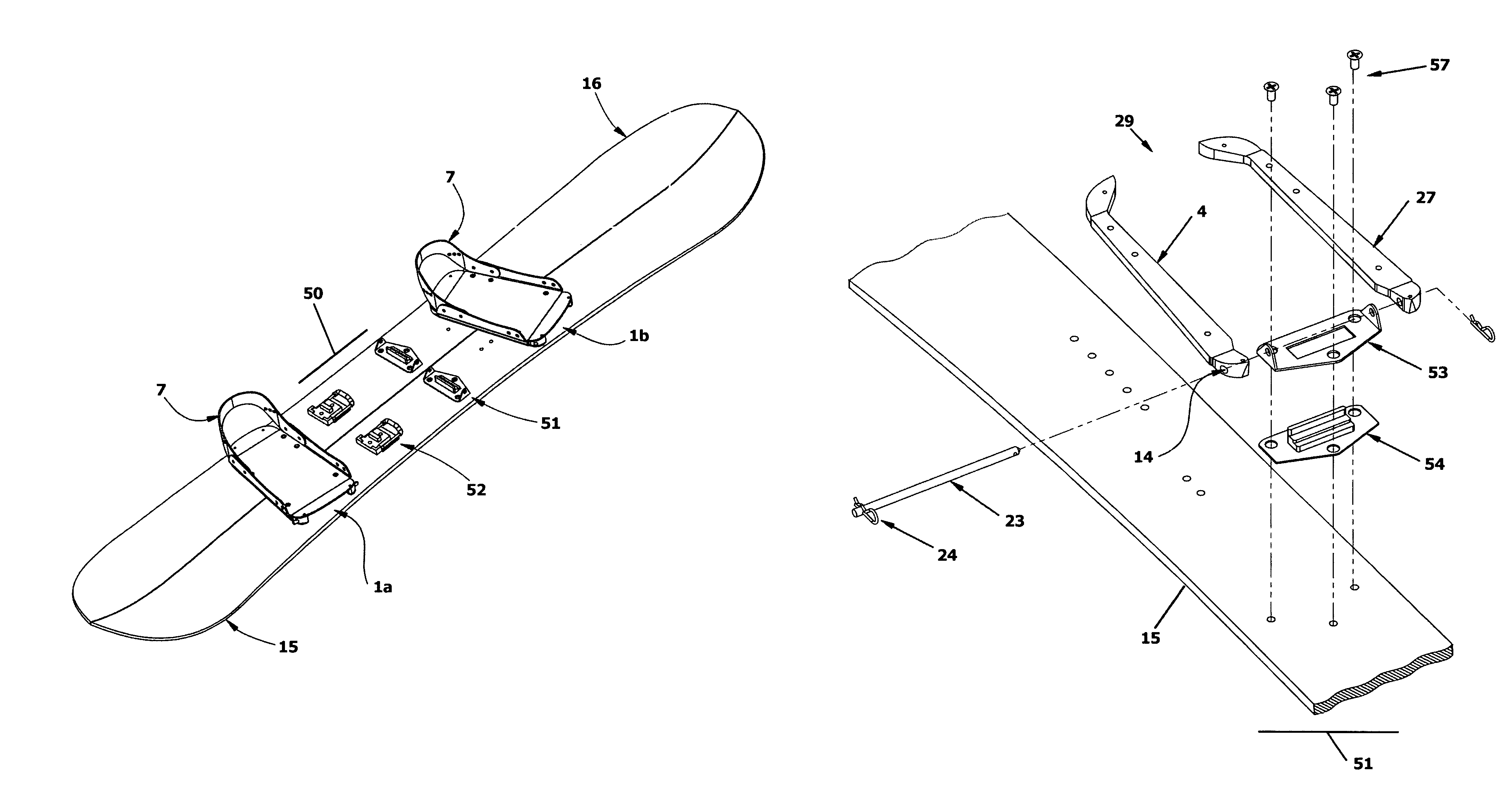
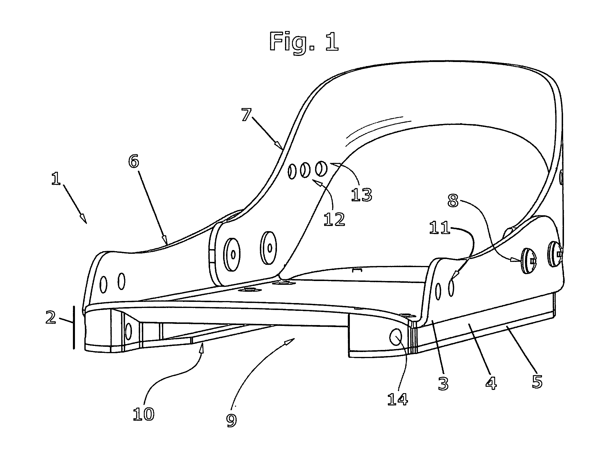
[0125]A Drake F-60 snowboard binding with integral heel cup and highback was modified in a shop by removing the base plate and 4-hole disk and substituting in their place a sheet of 2.5 mm aluminum with side rails folded up to form a shallow channel for the boot.

[0126]A three dimensional CAD design was sent to a local sheetmetal house that used a CNC (computer numerically controlled) laser cutter to cut the outline and holes for the aluminum parts necessary for the bindings. Sheetmetal press brakes were then used to bend the channels of the bindings. Similarly, a CNC milling machine cut out the UHMW polyethylene spacers from a sheet of 16 mm thick plastic. This machine provided all holes, the outline, and contoured surfaces.

[0127]Using mounting bolts, the heel and toe straps and highback were secured in place. A total of 10 screws, countersunk, were placed at the circumference of the base along each side of the sandwich to secure the plastic spacer materials (webs) in position betwe...

example 2

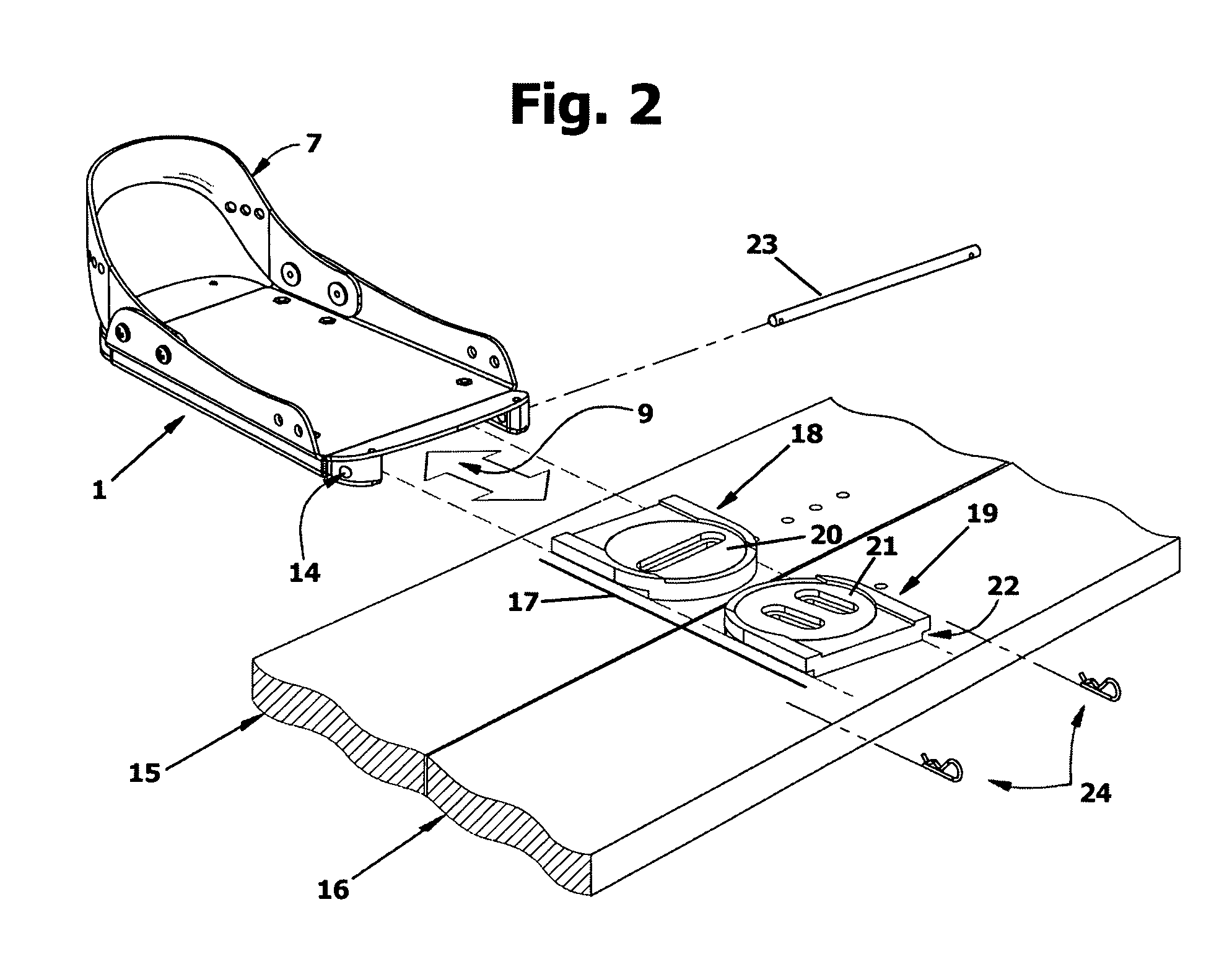
[0130]Mechanical comparisions were made using a splitboard and boot binding assembly of the prior art versus that of Example 1. A Voile “Splitdecision 166” splitboard was used for the comparisons, and for the prior art testing, Drake F-60 snowboard bindings were mounted as recommended by the manufacturer on the Voile mounting hardware. The boot bindings were assembled in snowboard riding configuration for these comparisons.

[0131]Physical measurements of the two boot bindings were also made and are recorded in Table 1.

[0132]

TABLE 1Prior ArtExample 1Distance from plane of board to bottom of26mm14mmbootWidth in contact with board under lateral80mm120mmloadWeight per boot binding1182g1015g

[0133]To measure deformation under lateral strain, which is related to spring constant K of the boot bindings, the snowboard was clamped to a vertical surface so that the highback of the boot bindings were mounted parallel to the floor. An 11.3 kg weight was then clipped onto the top of the highback, a...

example 3

[0137]A block of UHMWPE, 25 mm thick by 100 mm by 75 mm, is trimmed to fit between the lateral and medial spacers of an integral boot binding lower of FIG. 10. The rear height of the block is trimmed and rounded to fit easily under the toe riser. A thin rectangular pad is formed from the front of the block to protect the board surface from abrasion by the toe riser and serve as a shim during telemark ski touring. Using the boot bindings toe pivot holes of Example 1 as a drill guide, a transverse hole through the block is made. This hole is dimensioned to accept a captive bushing (see for example FIG. 21) for use with the longer toe pivot pins. Board mounting holes are also drilled and countersunk, so that the new toe mounting assembly can be fitted onto the existing inserts of the board. A second block is shaped for the other board. These components go into a boot binding interface conversion kit, or “split kit”, for use with the integral boot binding lower of the invention.

[0138]

TA...


PUM


Abstract

Improved boot bindings for backcountry splitboarding are disclosed. Each of a pair of soft-boot bindings has an integral boot binding lower that conjoins the two halves of a splitboard without the additional weight or height of an adaptor mounting plate and extra fasteners. Attached to the integral boot binding lower are the elements of a boot binding upper. The integral boot binding lower, in combination with upper boot bindings, provides improved torsional stiffness for splitboard riding. The integral boot binding lower further includes a toe pivot for free heel ski touring. The boot bindings can be readily detached from the ski touring position and reattached to the snowboard riding position, or vice versa, as is advantageous in backcountry touring and riding.

Description

RELATED APPLICATIONS[0001]This application claims the benefit under 35 U.S.C. 119(e) of U.S. Provisional Patent Application No. 60 / 783,327 filed Mar. 17, 2006 and U.S. Provisional Patent Application No. 60 / 792,231 filed Apr 14, 2006, and these provisional applications are incorporated herein by reference in entirety.BACKGROUND OF THE INVENTION[0002]1. Field of the Invention[0003]The invention relates generally to splitboards in Class 280 / 600 et seq. More particularly, the invention relates to a boot binding system that has improved torsional stiffness for use with splitboards and that gains its stiffness from an integral sandwich box girder construction which grippingly attaches to the snowboard mounting block assemblies.[0004]2. Background of the Invention[0005]Backcountry snowboarding appeals to riders who wish to ride untracked snow, avoid the crowds of commercial resorts, and spurn limitations on what and where they can ride. There are no ski-lifts in the backcountry, so the sno...

Claims


Application Information

Patent Timeline
Patent Type & Authority Patents(United States)
IPC IPC(8): A63C9/00
CPCA63C5/02A63C5/03A63C10/14A63C2203/06
Inventor RITTER, WILLIAM J
Owner SPARK R&D IP HLDG LLC
Why Eureka
Try Eureka