Vehicle twist axle assembly

a technology of twist axles and axles, which is applied in the direction of vehicle components, interconnection systems, resilient suspensions, etc., can solve the problems of compromising the structural integrity of joints and abrupt changes in torsional stiffness, and achieve the effect of increasing torsional stiffness

Active Publication Date: 2018-02-01
MAGNA INTERNATIONAL INC
View PDF6 Cites 6 Cited by
  • Summary
  • Abstract
  • Description
  • Claims
  • Application Information

AI Technical Summary

Benefits of technology

[0006]One aspect of the present invention is for a twist axle assembly for use in a vehicle. The twist axle assembly includes a pair of spaced apart trailing arms and a twist beam of a single piece which extends in a first direction between opposite ends that are operably connected with the trailing arms. The twist beam includes a pair of end portions and a middle portion which extends between the end portions. The twist beam further has a pair of side walls and at least one additional wall that extends between the side walls. The twist beam is generally hour-glass shaped with the middle portion having a first width in a second direction that is generally transverse to the first directions and the end portions have a greater second width in the second direction. The twist beam also tapers from the first width of the middle portion to the second widths of the end portions for gradually increasing a torsional stiffness from the middle portion to the end portions.

Problems solved by technology

However, this configuration may result in abrupt changes in torsional stiffness about the twisting axis at the joints between the twist beam and the trailing arms, and these abrupt changes in the torsional stiffness of the twist axle assembly at these joints could compromise the structural integrity of the joints.

Method used


Image

  • Vehicle twist axle assembly
  • Vehicle twist axle assembly
  • Vehicle twist axle assembly

Examples


Embodiment Construction

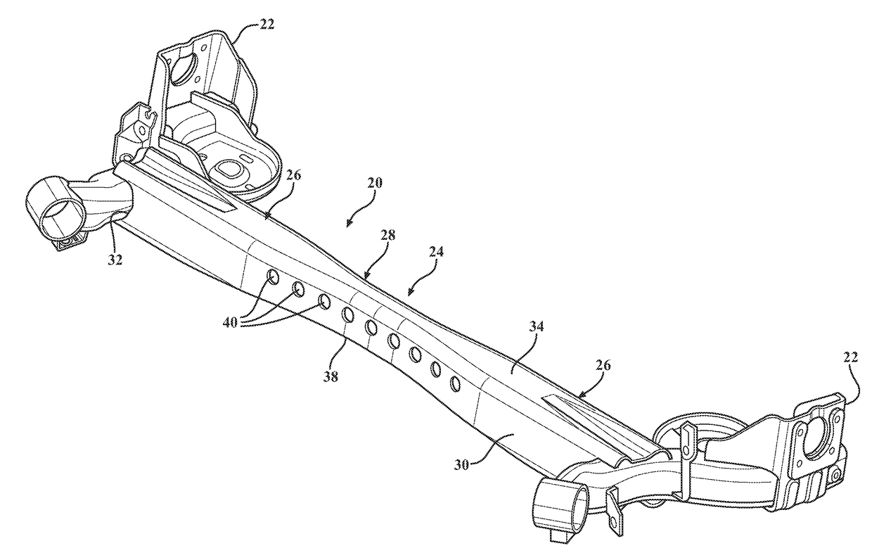
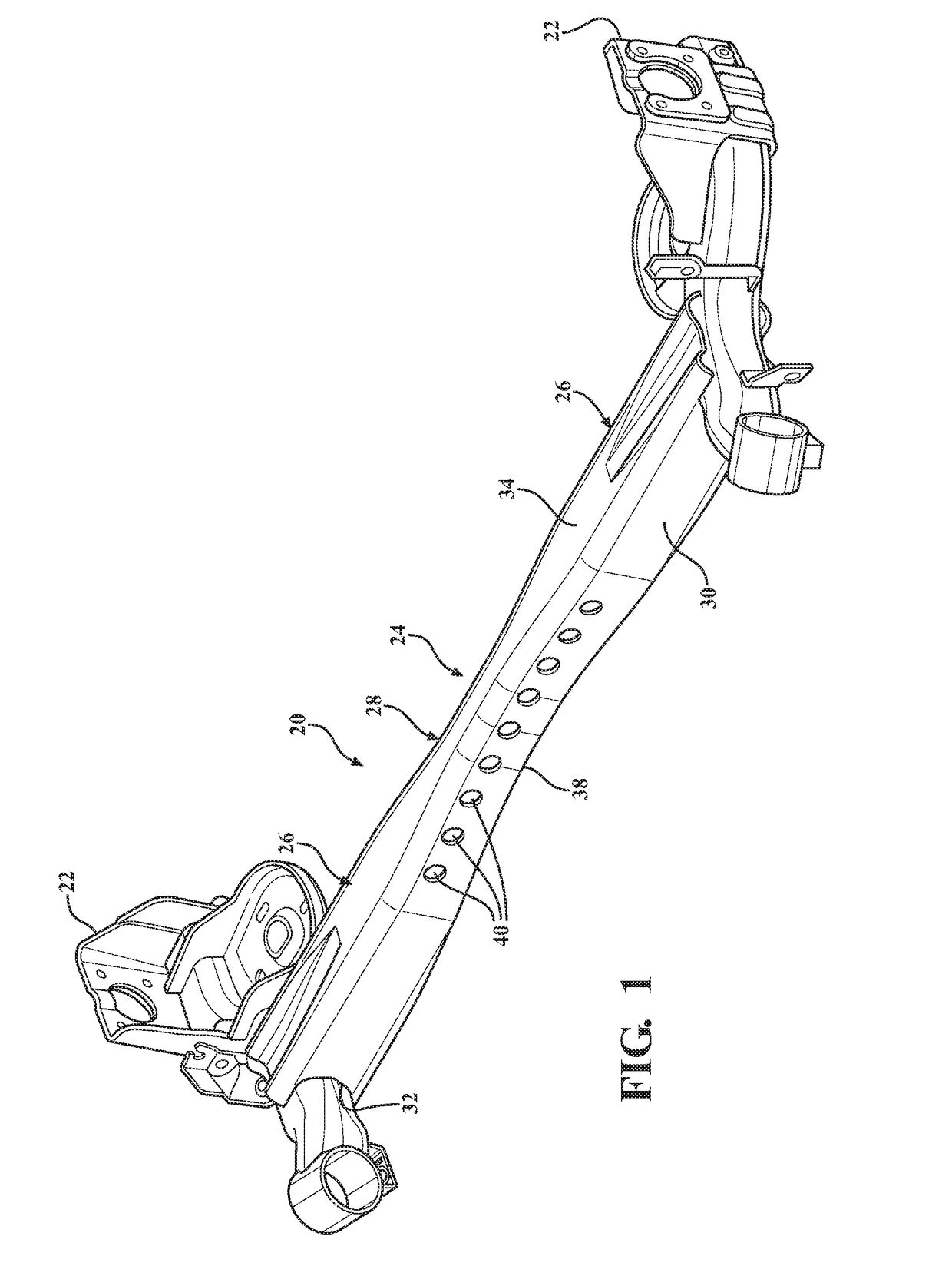
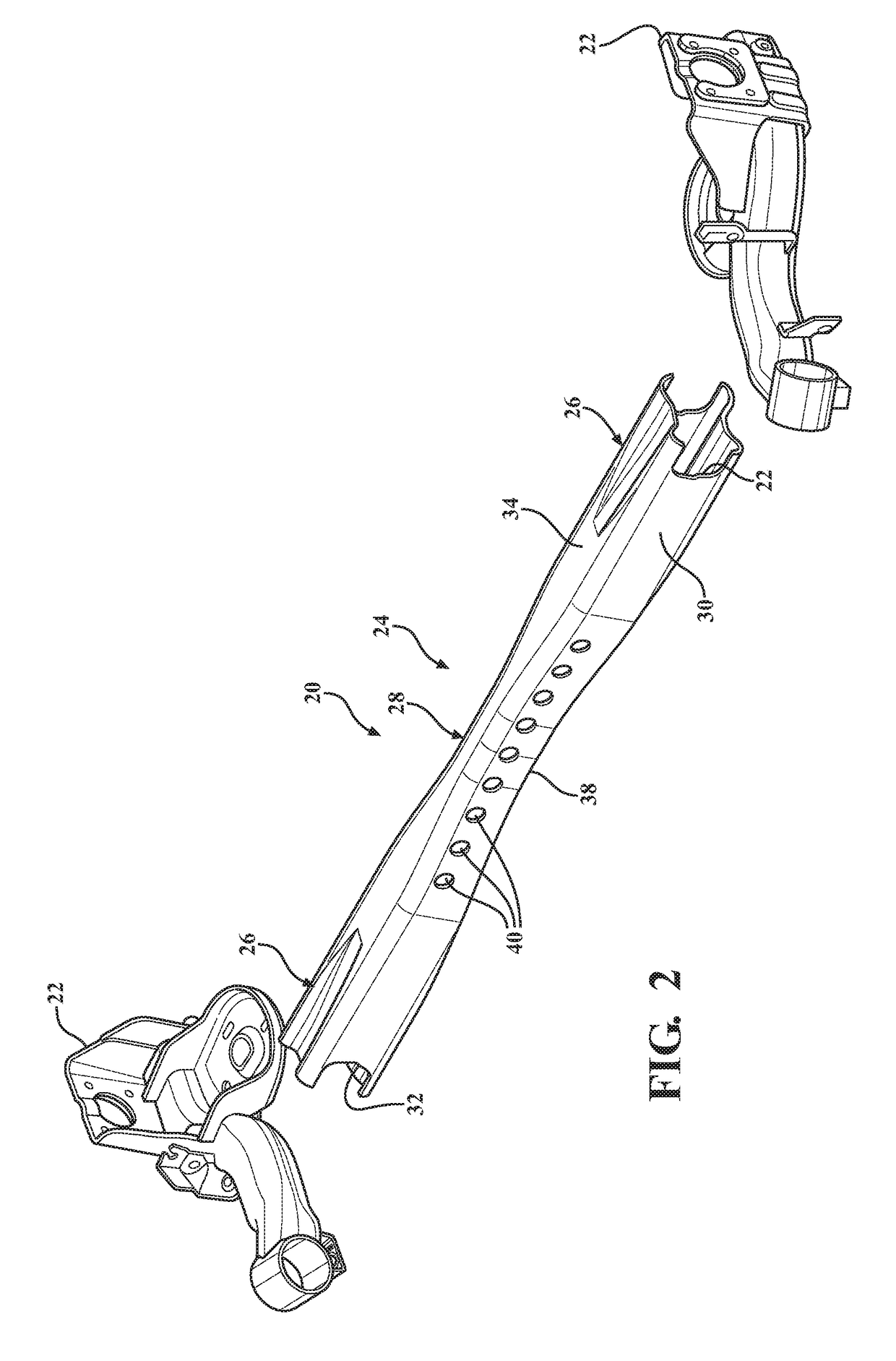
[0034]Referring to the Figures, wherein like numerals indicate corresponding parts throughout the several views, a first exemplary embodiment of an improved twist axle assembly 20 for a vehicle suspension system is generally shown in FIGS. 1-6. The twist axle assembly 20 includes a pair of trailing arms 22 and a twist beam 24 (also known as a cross-member) that extends in a lateral direction (which, in use, corresponds with a lateral direction of a vehicle) between the trailing arms 22. The trailing arms 22 are configured for attachment with opposing wheels of the vehicle, and in use, the trailing arms 22 pivot relative to one another in response to the vehicle rolling while cornering at speed or in response to the wheels encountering an object, such as a pot hole. The twist beam 24 resists the relative rotation of the trailing arms 22 to reduce roll and generally improve the performance of the vehicle's dynamics.

[0035]The twist beam 24 extends in a first direction between opposite ...


PUM


Abstract

The twist axle assembly includes a pair of spaced apart trailing arms and a twist beam of which extends in a first direction between the trailing arms. The twist beam includes a pair of end portions and a middle portion. The twist beam further has a pair of side walls and at least one additional wall that extends between the side walls. The side walls in the middle portion are generally parallel with the side walls of the end portions. The twist beam is generally hour-glass shaped with the middle portion having a first width and the end portions have a greater second width. The twist beam also tapers from the first width of the middle portion to the second widths of the end portions for gradually increasing a torsional stiffness from the middle portion to the end portions.

Description

CROSS REFERENCE TO RELATED APPLICATIONS[0001]This PCT Patent Application claims the benefit of and priority to U.S. Provisional Patent Application Ser. No. 62 / 118,748 filed Feb. 20, 2015, the entire disclosure of the application being considered part of the disclosure of this application, and hereby incorporated by reference.BACKGROUND OF THE INVENTION1. Field of the Invention[0002]The present invention is related, generally, to vehicle twist axle assemblies.2. Related Art[0003]A twist beam rear axle suspension assembly, also known as a torsion axle assembly, is a type of automobile suspension system including a pair of trailing arms, each of which is coupled with a wheel of a vehicle and with an axle of the vehicle, and a twist beam which extends transversely between the trailing arms. During operation of the vehicle, the twist beam deforms in a twisting movement when one of the wheels moves relative to another, such as during vehicle body roll or when one of the wheels encounters,...

Claims


Application Information

Patent Timeline
Patent Type & Authority Applications(United States)
IPC IPC(8): B60G21/05B60G11/18
CPCB60G21/051B60G11/183B60G2200/21B60G2206/8102B60G2206/8201B60G2200/23B60G2206/20B60G2206/202B60B35/001B60B35/125
Inventor CHELIKANI, ABHINANDMORITZ, PATRICK DANIELHALBAUER, JOHANNES PETERSINGH, SUKHDEEPLANGWORTHY, KEVIN RICHARD
Owner MAGNA INTERNATIONAL INC
Why Eureka
Try Eureka