Planetary gear, gear motor and series of gear motors

a technology of planetary gear and gear motor, which is applied in the direction of toothed gearings, dynamo-electric machines, electrical apparatus, etc., can solve the problems of difficult and expensive to satisfactorily true the output shaft of planetary gear, difficult to lubricate sealing elements, and the sun-wheel shaft is far away from the motor, so as to achieve high manufacturing precision and optimize tolerances , the effect of keeping costs as low

Inactive Publication Date: 2007-02-27
SEW-EURODRIVE GMBH & CO KG
View PDF17 Cites 34 Cited by
  • Summary
  • Abstract
  • Description
  • Claims
  • Application Information

AI Technical Summary

Benefits of technology

[0006]In this context, an interface for connection to further components may be provided. Thus, the planetary-gear stage may be connected to different electric motors, couplings, clutches or other gear stages, etc. This may allow the planetary-gear stage to be used in different variants within a size of the series. In this manner, a reduction in the number of separate parts may be achieved, and the cost of producing the planetary-gear stage and the corresponding series may be reduced. In view of the fact that the gears are assembled all over the world, a reduction in the variety of parts may be desired. It may also be provided that the overall length is reduced, since the connectible components are adapted and adjusted to each other, which means that, e.g., savings of housing parts and optimization of the mass moment of inertia are possible.
[0021]Therefore, a series of drive units may be provided, whose variants have a high, maximum allowable, transverse force and an increased torsional stiffness.

Problems solved by technology

In this context, it may be disadvantageous that the bearing for the sun-wheel shaft is far away from the motor to be attached.
In addition, it may be difficult and expensive to satisfactorily true the output shaft for the planetary gear.
It may also be disadvantageous that the sealing element is difficult to lubricate, since it is separated from the interior of the gear by bearing 28.
This may have a negative effect on the rigidity and torsional stiffness.
The planet carrier is supported against the gear housing and therefore requires a large, expensive bearing 30.
In the case of low gear ratios i, i.e., a large sun gear, it may be difficult and, under some circumstances, even impossible to mount the sun gear.
This may reduce the bearing and seal power losses and consequently may reduce the heat generation.

Method used


Image

  • Planetary gear, gear motor and series of gear motors
  • Planetary gear, gear motor and series of gear motors
  • Planetary gear, gear motor and series of gear motors

Examples


Embodiment Construction

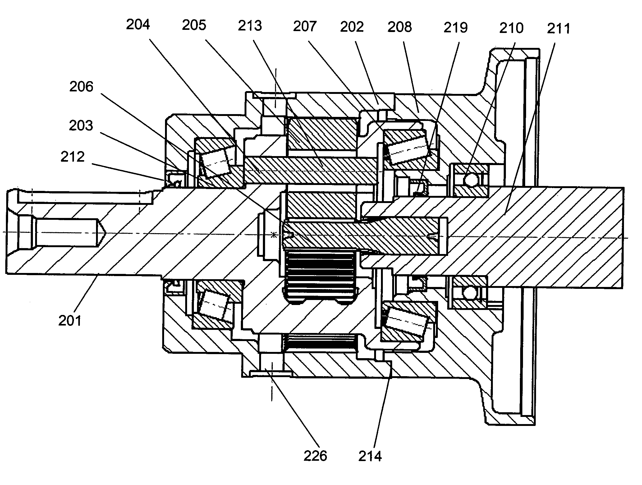
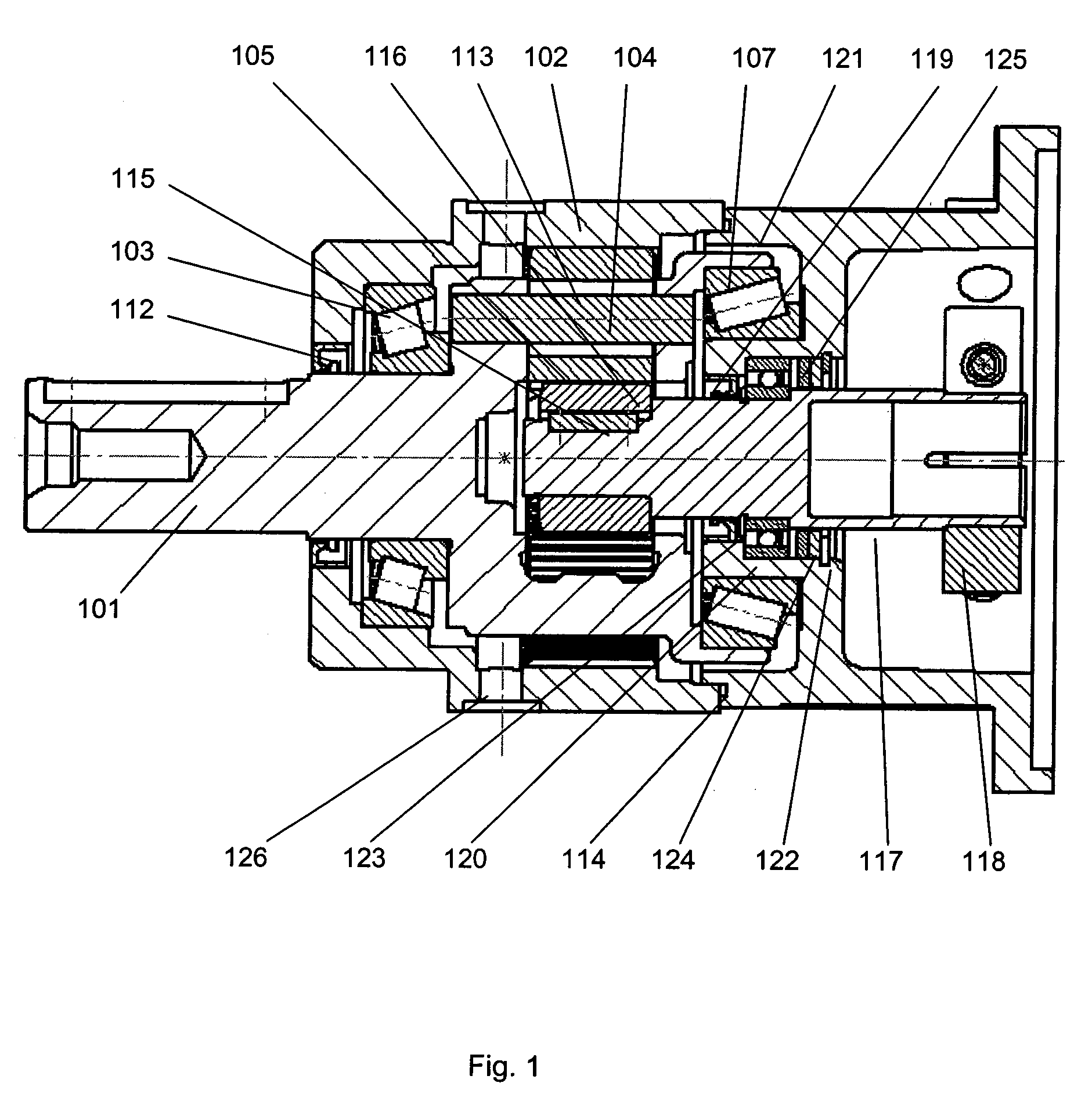
[0030]Shown in FIG. 1 is an exemplary embodiment of a single-stage variant of the series. Output-side planet carrier 101 is supported in gear housing 102 by power-takeoff bearing 103 and is driven by planet bolts 104 that support planet bearing 113. Planet wheels 105 supported on planet bearings 113 mesh with sun wheel 106, which, as a slip-on pinion, is form-locked to the motor shaft by a feather-key connection 115. Power-takeoff bearing B 107 inwardly supports planet carrier 101 in clutch housing 121 of the motor. Therefore, power-takeoff bearing B 107 acts on a smaller diameter and is therefore designed to be smaller, more compact, and more cost-effective than those that are conventional.

[0031]Clutch bearing 120, which braces clutch shaft 117 against clutch housing 121, also lies in the same axial region as the receiving region of power-takeoff bearing B 107. This clutch bearing 120 is seated on a diameter, which is reduced in comparison with the diameter of the clutch shaft in t...


PUM


Abstract

A series of gear motors, a gear motor, and a planetary-gear stage includes planet wheels that mesh with a sun wheel and inner gear teeth provided for the gear housing. The planet wheels are supported in a rotatable planet carrier, which forms the power take-off, and to which a sealing element is assigned on the output side. The planetary-gear stage is assigned a further sealing element on the input side. The gear housing is shaped on the input side such that an interface is formed for connection to further components, which include at least one shaft connected to the sun wheel.

Description

FIELD OF THE INVENTION[0001]The present invention relates to a planetary gear, a gear motor, and a series of gear motors.BACKGROUND INFORMATION[0002]German Published Patent Application No. 199 56 789 describes a planetary gear, which is designed to be attached to an electric motor and has a compact construction. In particular, a sealing element, which seals the sun-wheel shaft from the external space, is situated on an outer diameter that is reduced in comparison with the receiving region for the output shaft of the electric motor, which means that the heat generation may be reduced. In this context, it may be disadvantageous that the bearing for the sun-wheel shaft is far away from the motor to be attached. In addition, it may be difficult and expensive to satisfactorily true the output shaft for the planetary gear. And, despite the reduction in diameter, the heat generation in the sealing element and bearing 28 is considerable at high input speeds, such as those which often occur ...

Claims


Application Information

Patent Timeline
Patent Type & Authority Patents(United States)
IPC IPC(8): F16H57/08F16H1/28F16H1/46F16H57/029F16H57/033H02K7/116
CPCF16H1/28F16H57/029H02K7/116F16H57/033F16H1/46Y10T74/2186F16H2057/0335
Inventor CHRIST, MICHAELZIMMERMANNKASPER, JURGEN
Owner SEW-EURODRIVE GMBH & CO KG
Why Eureka
Try Eureka