Wing with pneumatic reverse effect

An aerodynamic and aerodynamic technology, which is applied in the directions of wings, multi-layer structures, chords/stringers, etc., can solve the problems of inability to use engineering applications, and achieves easy-to-center position, convenient production, and compact structure. Effect

Inactive Publication Date: 2009-05-06
BEIHANG UNIV
View PDF0 Cites 6 Cited by
  • Summary
  • Abstract
  • Description
  • Claims
  • Application Information

AI Technical Summary

Problems solved by technology

But so far no one has developed a device for manipulating the reverse effect, which not only has an adverse effect on further research on the reverse effect phenomenon, but also makes it impossible to talk about the engineering utilization of the reverse effect phenomenon

Method used


Image

  • Wing with pneumatic reverse effect
  • Wing with pneumatic reverse effect
  • Wing with pneumatic reverse effect

Examples


example

[0064] The relevant parameters of the wind tunnel used in the experiment:

[0065] Experimental section size: length - 3.5m, width - 1.5m, height - 1.5m, shrinkage ratio - 9;

[0066] Wind speed in the experimental section: V 0 =10~80m / s; Re=1.03×10 5 ~8.2×10 5 ;

[0067] Closed design wind speed in the experimental section: V 0 =80m / s;

[0068] Design wind speed of the opening of the experimental section: V 0 =60m / s; (this experiment uses the opening experiment)

[0069] Closed turbulence: ε=0.08%;

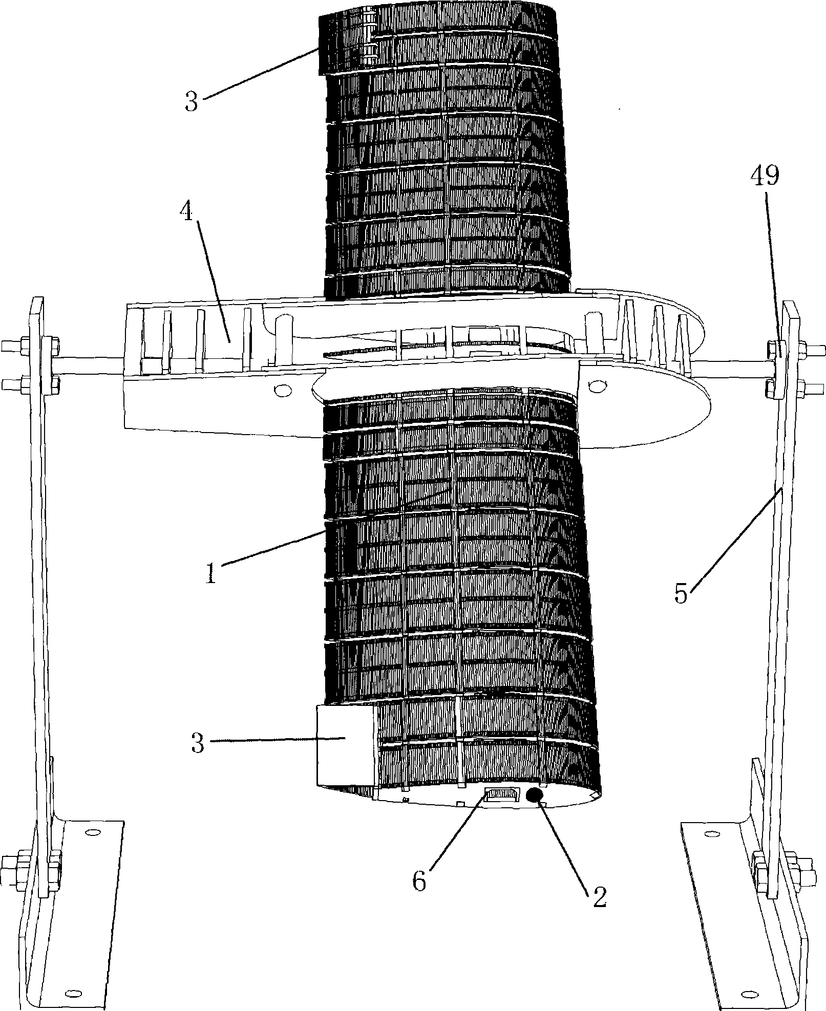
[0070] Fix the generator on the test bench and place it in the wind tunnel to blow air. The initial wind speed of the wind tunnel is set to 10m / s. Looking from the front of the generator, the generator rolls clockwise at this time; gradually increases Wind speed, when the wind speed is less than 20m / s, the generator keeps rolling clockwise; but when the wind speed is closer to 20m / s, the generator roll speed drops very low, when the wind speed reaches 20m / s, the roll spee...


PUM


Abstract

The invention provides a pneumatic anti-effect wing comprising a flexible wing which comprises a plurality of wing sections arranged in parallel and a flexible wing beam threaded through the plurality of wing sections. The invention also provides a pneumatic anti-effect generator comprising a support device and the flexible wing which is rotationally coupled with the support device. The pneumatic anti-effect wing can conveniently generate the distinct manipulated anti-effect phenomenon. Wherein, the singly threaded wing beam and the wing sections lead the torsional rigidity and rigidity center of the wing to be manipulated easily; an opening beam is adopted as the singly threaded wing beam to lead the wing to get a smaller torsional rigidity and an enough flexible rigidity so as to lead the generator to generate the manipulated anti-effect phenomenon under a lower wind speed; sub wings with the different symmetrical deflection can be adopted so as to demonstrate that the anti-effect speed of the manipulated anti-effect is not impacted by the deflection of the sub wings; and a chuck-style body leads the generator to be characterized in that the wings can be conveniently demounted and displaced.

Description

technical field [0001] The invention relates to a control anti-effect generator, in particular to a wing with aerodynamic anti-effect in the field of aeroelasticity. Background technique [0002] Manipulation reverse effect is a topic that has been deeply researched in the field of aeroelasticity, and the mechanism and preventive measures of reverse effect have also been successfully explored. But so far no one has developed a device for manipulating the reverse effect, which not only has an adverse effect on further research on the reverse effect phenomenon, but also makes it impossible to talk about the engineering utilization of the reverse effect phenomenon. [0003] How to design a manipulation anti-effect generator so that it can meet the following requirements is one of the problems to be solved urgently: [0004] (1) Complete reasonable scheme design and accurate calculation, and on this basis, produce an actual manipulation anti-effect generator that is consistent ...

Claims


Application Information

Patent Timeline
Patent Type & Authority Applications(China)
IPC IPC(8): B64C3/00B64C3/18B64C3/20B64C1/00
Inventor 吴志刚陈洪磊杨超
Owner BEIHANG UNIV
Why Eureka
Try Eureka