Electric power steering system for vehicle and utility vehicle therewith

a technology of electric power steering and vehicle, which is applied in the direction of power steering, electric steering, vehicle components, etc., can solve the problems of weak power performance of electric power assist devices, increased engine power loss of hydraulic pumps, and inability to effectively use space, etc., to achieve convenient disassembly and effective utilization of space

a technology of electric power steering and vehicle, which is applied in the direction of power steering, electric steering, vehicle components, etc., can solve the problems of weak power performance of electric power assist devices, increased engine power loss of hydraulic pumps, and inability to effectively use space, etc., to achieve convenient disassembly and effective utilization of space

US7900743B2Active Publication Date: 2011-03-08KAWASAKI MOTORS LTD

Image

  • Electric power steering system for vehicle and utility vehicle therewith
  • Electric power steering system for vehicle and utility vehicle therewith
  • Electric power steering system for vehicle and utility vehicle therewith

Examples


embodiment

Preferred Embodiment

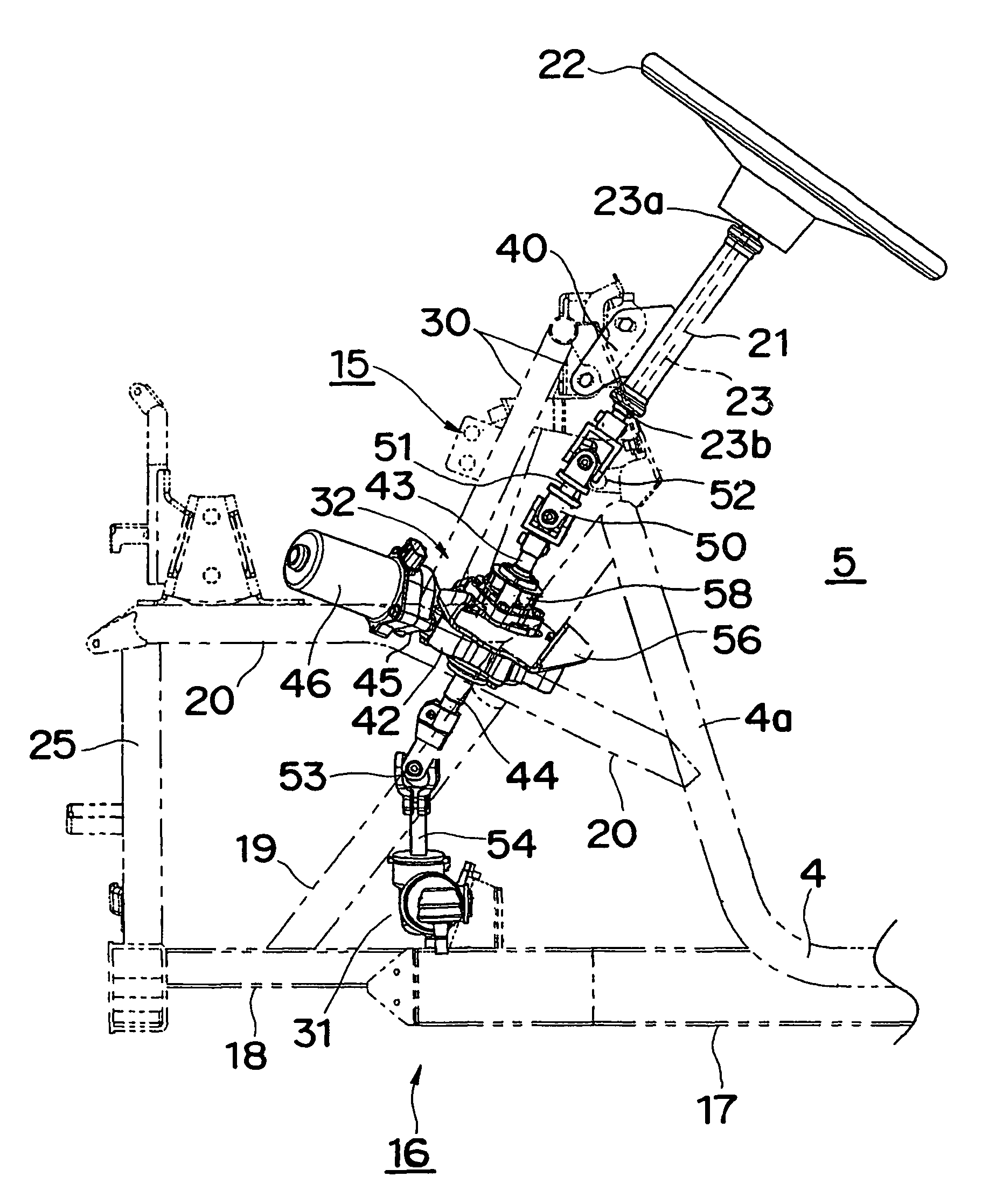
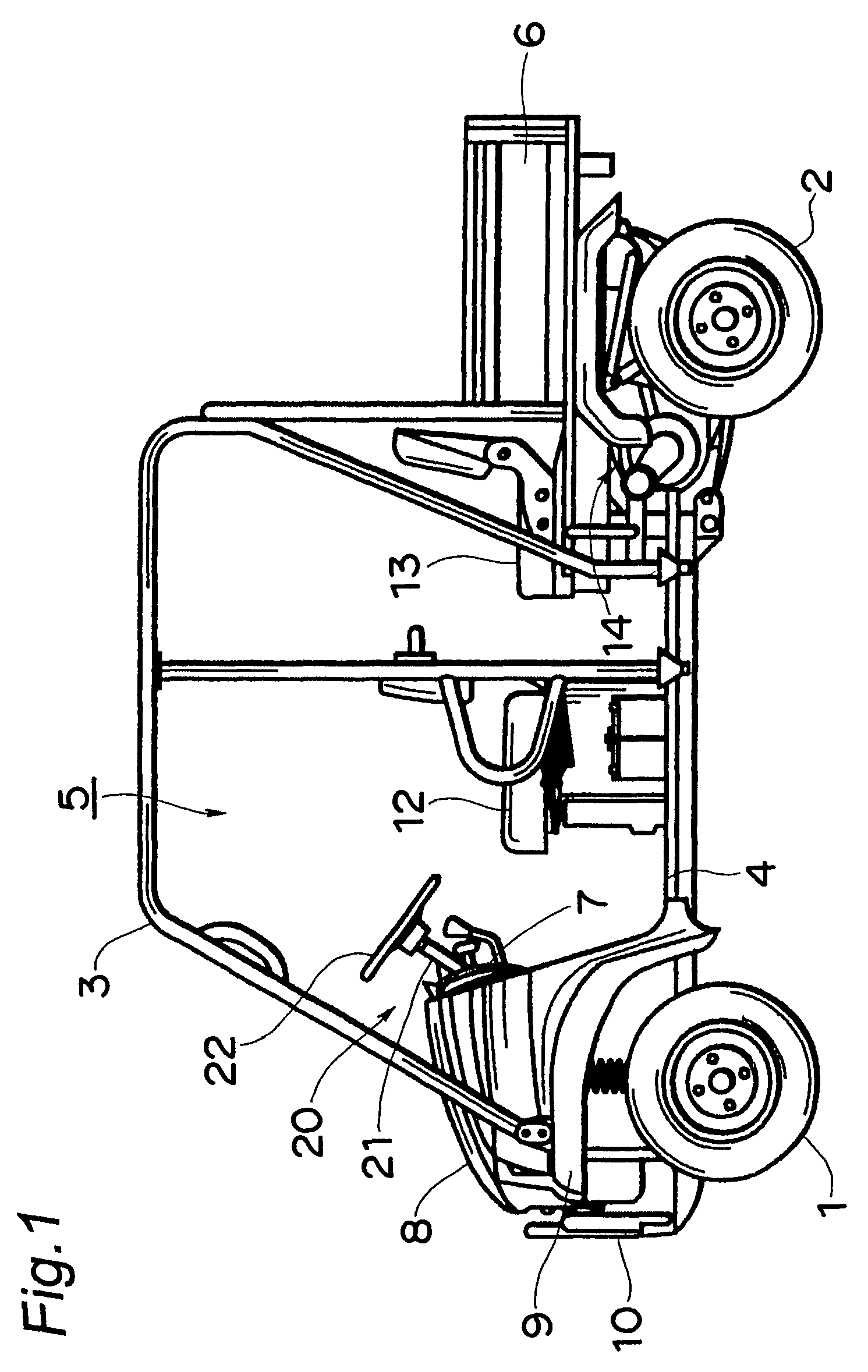
[0031]FIGS. 1 to 6 show an electric power steering system for a vehicle and a four wheeled utility vehicle provided with the same in one preferred embodiment according to the present invention. The present invention will be described below in reference to FIGS. 1 to 6.

(Configuration of Entire Vehicle)

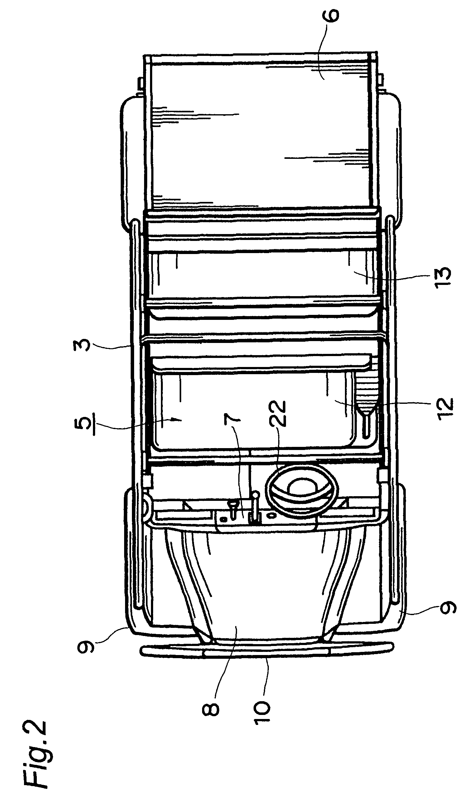
[0032]FIG. 1 is a left side view showing the four wheeled utility vehicle, which is provided with a pair of right and left front wheels 1 in the front portion of the vehicle, a pair of right and left rear wheels 2 in the rear portion of the vehicle, a cabin 5 defined between the front wheels 1 and the rear wheels 2 and constituted of a metallic cabin frame 4, a carrier 6 disposed behind the cabin 5, a bonnet 8 disposed in front of the cabin 5, a pair of right and left front fenders 9 disposed in front of the cabin 5, and a bumper 10 in front of the bonnet 8. The upper portion of the cabin 5 is covered with a protecting frame 3 made of a metallic pipe.

[0033]A bench-ty...


PUM


Abstract

An electric power assist device can be compactly disposed with ease in an electric power steering system for a vehicle. The electric power steering system for a vehicle includes: a steering wheel; a steering column incorporating therein a steering shaft connected to the steering wheel and extending downward to the front; and an electric power assist device for assisting a steering torque of the steering wheel. Here, an input shaft and an output shaft of the electric power assist device are connected to the lower end of the steering shaft and the input shaft of the steering gear device, respectively, via universal joints.

Description

BACKGROUND OF THE INVENTION[0001]I. Technical Field of the Invention[0002]The present invention relates to an electric power steering system for a vehicle and a four wheeled multi use light traveling vehicle provided with the same and, more particularly, to an electric power steering system for a vehicle provided with an electric power assist device including an electric motor.[0003]II. Description of Related Art[0004]Typical examples of a power assist device of a power steering system for a vehicle include a hydraulic power assist device having a hydraulic pump and an electric power assist device having an electric motor.[0005]At present, the hydraulic power assist device has prevailed, with the advantages of great power performance and freedom of arrangement of hydraulic equipment, such as a hydraulic pump at a desired position by use of a hydraulic hose. However, since periodic inspection of the device for an oil leakage or the like is required, maintenance on the device takes si...

Claims


Application Information

Patent Timeline
08 Mar 2011
Publication
US7900743B2
IPC
B62D5/04
CPC
B62D5/04
Inventors
KAKU, HIDETOSHI; HISADA, KAZUMASA