Ball screw module

a technology of ball screw and screw shaft, which is applied in the direction of gearing, mechanical equipment, hoisting equipment, etc., can solve the problems of shortening affecting the service life of the screw shaft, and causing a lot of nois

Active Publication Date: 2011-03-22
HIWIN TECH
View PDF10 Cites 6 Cited by
  • Summary
  • Abstract
  • Description
  • Claims
  • Application Information

AI Technical Summary

Benefits of technology

[0008]To solve the aforesaid problems, it is the primary objective of the present invention to provide a ball screw module comprising a ball connector revolving smoothly in a nut member so as to achieve high performance and high preciseness of the ball screw module.
[0010]Yet another objective of the present invention is to provide a ball screw module comprising a circulating device having two guiding grooves configured to guide a ball connector through a course of movement and specially designed with regard to turning sections of a circulating route, allowing the ball connector to pass the turning sections smoothly without being pushed or dragged unduly.
[0012]Compared with the prior art, the ball screw module of the present invention has the following advantages: a circulating device of the ball screw module of the present invention has two guiding grooves specially designed in terms of radii of curvature with regard to turning sections, and thus at the turning sections in the circulating device the ball connector is guided through a three-dimensional turn along a specific path; and the two guiding grooves are substantially equal in length such that a first linking strap and a second linking strap of the ball connector are not unduly dragged or pushed when passing the turning sections.

Problems solved by technology

However, adjacent balls are, in the course of rolling, likely to collide with each other and therefore make much noise.
The collision shortens the service life of the balls and therefore shortens the service life of the screw shaft.
An improperly designed circulating route is likely to prevent a ball connector from passing a circulating route smoothly and changing direction.
Ball connectors disclosed in the prior art tend to sever when twisted and pulled unduly.
U.S. Pat. No. 5,993,064, failed to teach how to enable the ball connector to pass the circulating device smoothly.
If angles of a revolving route are not specially designed, a ball connector traveling along the revolving route is likely to have its inner side squeezed and its outer side pulled and therefore severed due to the different strain between its inner and outer sides in deformation.
Although linear rolling tracks using ball connectors are commercially available, ball screw shafts adopting ball connectors remain unavailable in terms of design and fabrication.

Method used


Image

  • Ball screw module
  • Ball screw module
  • Ball screw module

Examples


Embodiment Construction

[0028]The present invention is directed to a ball screw module based on mechanism transmission principles comprehensible to persons ordinarily skilled in the related art, and thus the related mechanism transmission principles are not described in detail hereunder. Also, the accompanying drawings solely serve an illustrative purpose and therefore are not drawn to scale.

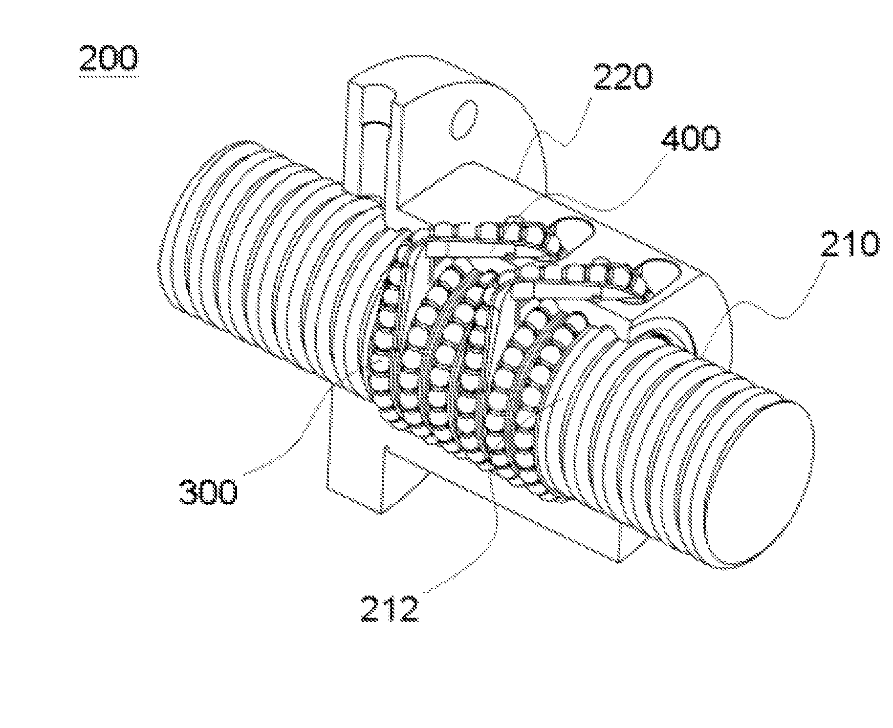
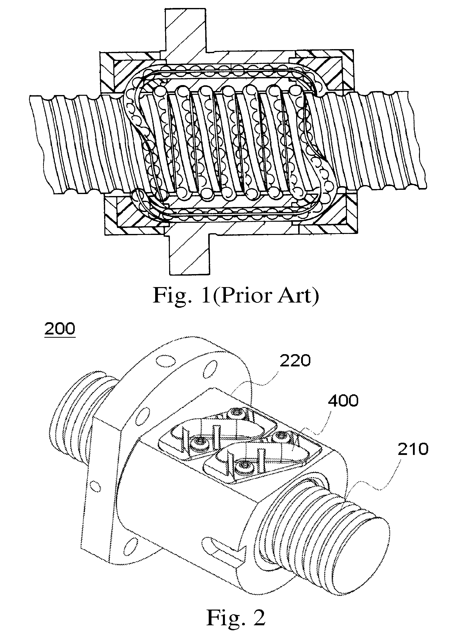
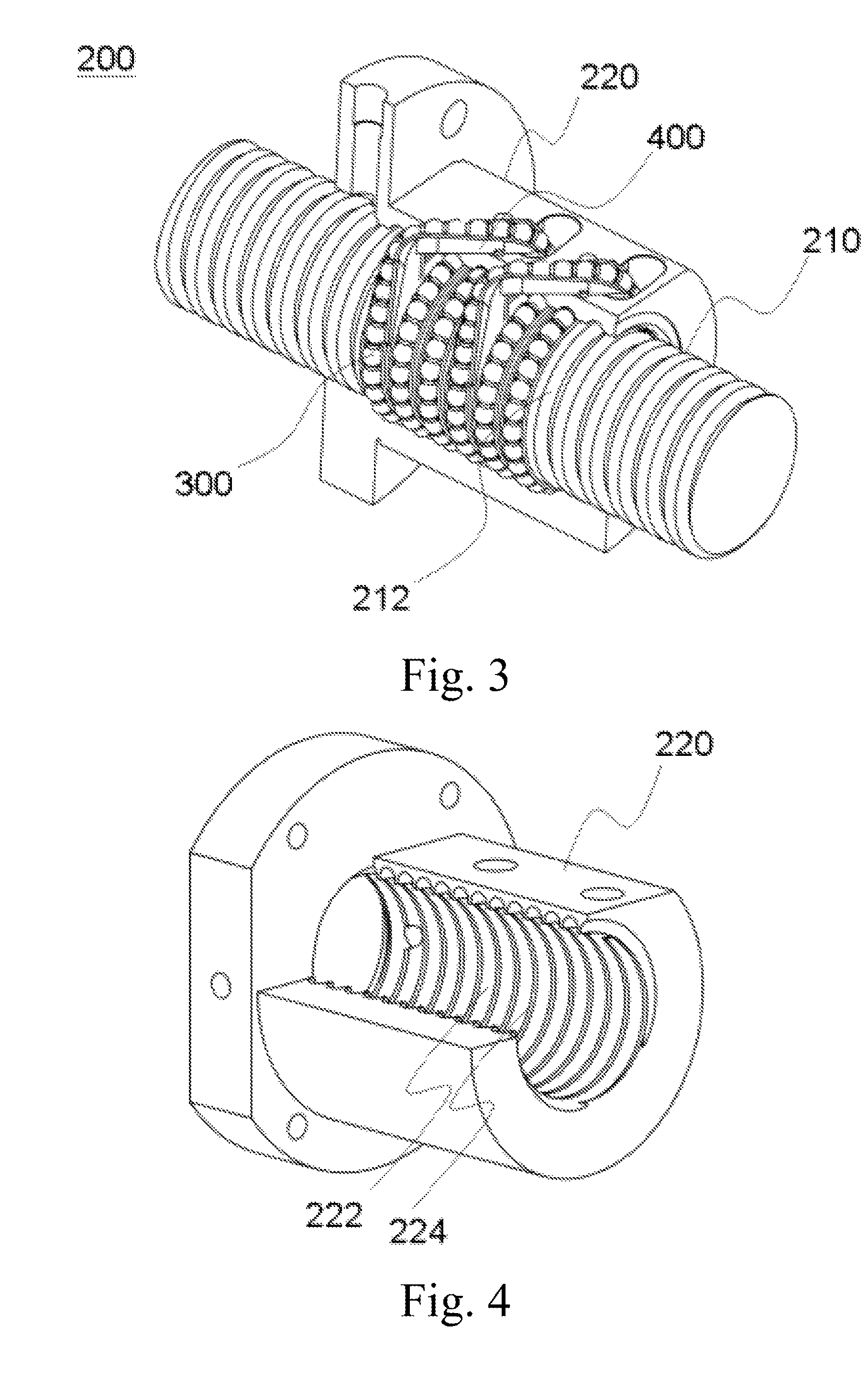
[0029]Referring to FIGS. 2, 3, 4 and 5, the present invention discloses a first preferred embodiment wherein a ball screw module 200 comprises a screw shaft 210, a nut member 220, a ball connector 300, and a circulating device 400. The screw shaft 210 has an outer surface provided with a spiral-shaped first load rolling groove 212. The nut member 220 is circumferentially disposed around the screw shaft 210 and has an inner surface provided with a spiral-shaped second load rolling groove 222 corresponding in position to the first load rolling groove 212. The first load rolling groove 212 and the second load rolling groo...


PUM


Abstract

Provided is a ball screw module including a screw shaft, a nut member, a ball connector, and a circulating device inside the nut member. The screw shaft and the nut member constitute a first load rolling groove. The circulating device, being connected with the first load rolling groove, has a first turning section and a second turning section, and includes a first guiding groove and a second guiding groove. The first guiding groove has a radius of curvature greater than that of the second guiding groove when the ball connector passes the first turning section. The first guiding groove has the radius of curvature smaller than that of the second guiding groove when the ball connector passes the second turning section.

Description

BACKGROUND OF THE INVENTION[0001]1. Field of the Invention[0002]The present invention relates to ball screw modules, and more particularly, to a ball screw module having a ball connector.[0003]2. Description of the Prior Art[0004]The operating principles of a conventional ball screw shaft involve providing balls between a screw shaft and a nut member so as to replace the sliding friction transmission of an outdated acme screw shaft (ACME) with ball rolling motion, thereby reducing friction-induced wear and tear greatly and maintaining high efficiency and high preciseness.[0005]Balls are effective in enabling a screw shaft to move smoothly. However, adjacent balls are, in the course of rolling, likely to collide with each other and therefore make much noise. The collision shortens the service life of the balls and therefore shortens the service life of the screw shaft.[0006]To solve the problems, the prior art disclosed a connector whereby balls are fixed in position. U.S. Pat. No. 5...

Claims


Application Information

Patent Timeline
Patent Type & Authority Patents(United States)
IPC IPC(8): F16H1/24
CPCF16H25/2214F16H25/2233Y10T74/19749Y10T74/19777F16C33/37
Inventor CHEN, YAN-YU
Owner HIWIN TECH
Why Eureka
Try Eureka