Operation controlling

a technology of operation control and electrical device, which is applied in the direction of pulse generator, pulse technique, substation equipment, etc., can solve the problems of irregular electrical power delivered to the device, negative effect on the operation of the digital circuit, and several non-ideal conditions, so as to achieve the effect of safe startup and shutdown process of the electrical devi

Active Publication Date: 2011-03-22
SEMICON COMPONENTS IND LLC
View PDF5 Cites 0 Cited by
  • Summary
  • Abstract
  • Description
  • Claims
  • Application Information

AI Technical Summary

Benefits of technology

[0005]It is the object of the invention to create a method pertaining to the technical field initially mentioned, that avoids the problems mentioned above and enables a safe startup and shutdown process of an electrical device.
[0007]Therefore, the threshold voltage for initiating the transition from one state to the other state of the electrical device is higher for a rising supply voltage than for a falling supply voltage. Hence, once the supply voltage has risen above the startup reference voltage, the supply voltage may vary without any undesired toggling of the electrical device between the enabled and the disabled states as long as it remains above the shutdown reference voltage. So the likelyhood of undesired operations or even damage of the electrical device can be reduced significantly.

Problems solved by technology

One of the problems that may arise with such devices is that the electrical power delivered to the device may show irregularities, for example during the startup and the shutdown process.
Several non-ideal conditions may be observed when the device is switched on or off or when a battery is inserted or removed.
However, with more complex devices such as for example devices including a digital circuit like contemporary listening devices these conditions may have a negative effect on the operation of its digital circuit.
They may for example cause undesired operations such as arithmetic operations of a digital processor or read / write operations of a memory block, for example an EEPROM (Electrically Erasable Programmable Read Only Memory).
Such conditions may even damage the device.
However, such switches do not eliminate the above problems when the battery is inserted or removed while the ON / OFF switch remains open or closed or when there is no ON / OFF switch at all.

Method used


Image

  • Operation controlling
  • Operation controlling
  • Operation controlling

Examples


Embodiment Construction

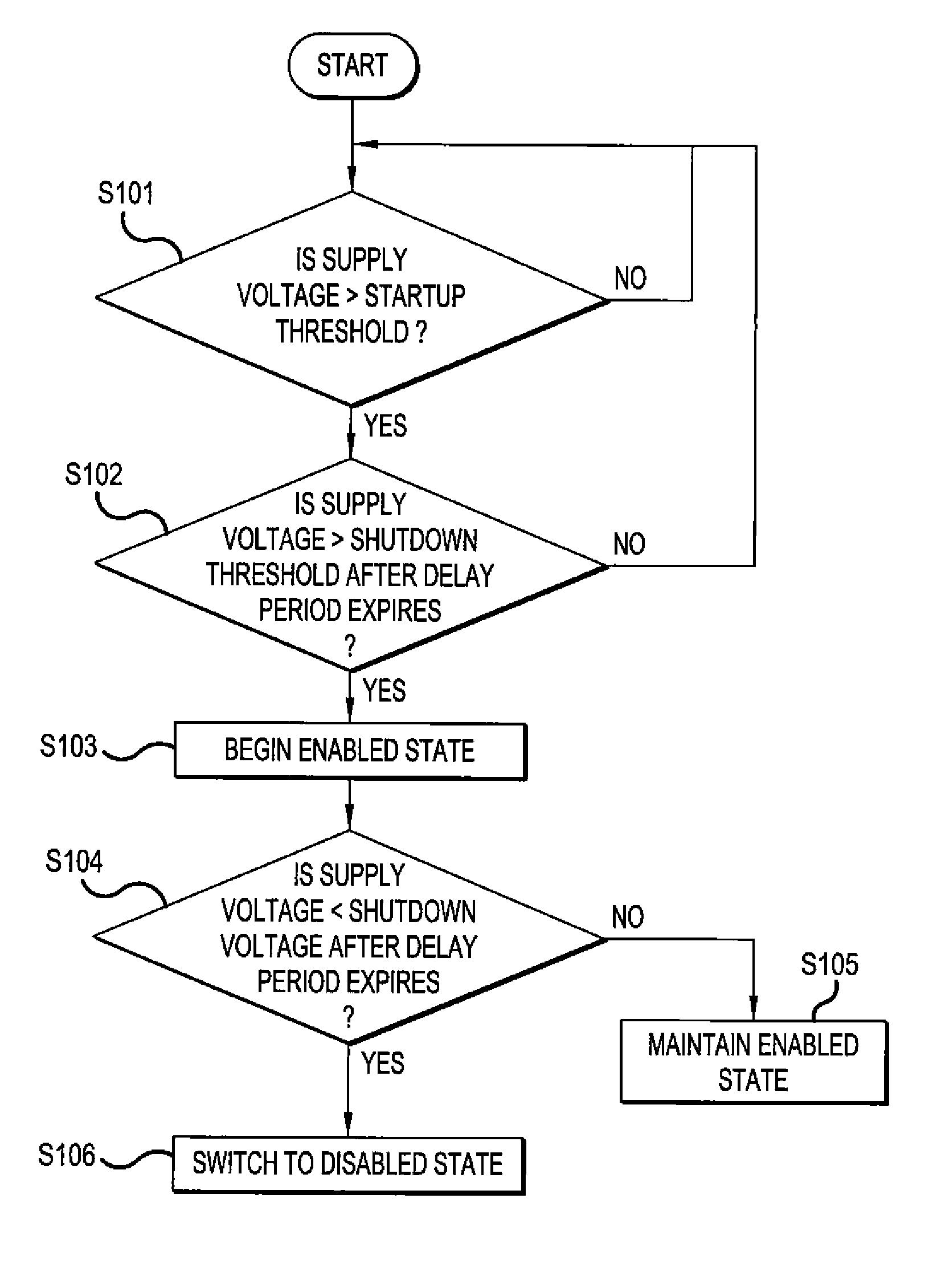
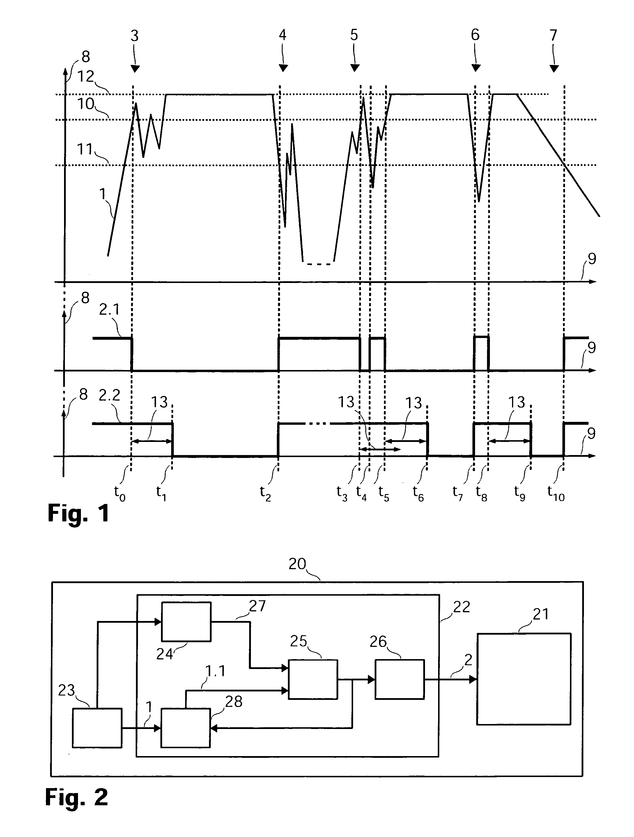
[0037]FIG. 1 schematically shows how a reset signal for controlling the operation of an electrical device, in this case of a hearing aid, is generated. FIG. 1 shows the supply voltage 1 of the hearing aid as voltage amplitude 8 against time 9. It further shows two different reset signals 2.1 and 2.2 generated according to the invention. Different phases are shown: a first startup phase 3, a shutdown phase 4, a second startup phase 5, a transient phase 6 and a dying phase 7.

[0038]The first startup phase 2 shows the supply voltage 1 when a battery is inserted into the hearing aid. During the first startup phase 2, the supply voltage 1 rises and oscillates undesirably. At the time t0 when the supply voltage 1 exceeds a startup threshold voltage 10, the first reset signal 2.1 changes its level from high to low. A high level of the reset signal means that the hearing aid is resetted and a low level of the reset signal means that the hearing aid is not resetted. As it is shown in FIG. 1, ...


PUM


Abstract

The invention deals with a controlling device (22) for an electrical device such as for example a hearing aid (20). The hearing aid (20) includes a power supply (23) and a functional unit (21) controlled by the controlling device (22) via a reset signal (2). In order to reduce undesired behavior of the hearing aid in case of transients, brown-out or other oscillations of the input voltage (1), the controlling device (22) is built such that the functional unit (21) is resetted as long as the rising supply voltage (1) is lower than a startup threshold. Once the functional unit (21) is enabled, it remains enabled as long as the supply voltage (1) does not fall below a shutdown threshold where the shutdown threshold voltage is lower than the startup threshold voltage. This hysteresis is implemented via a reference generator (24) generating a constant reference voltage (27) and a modifiable voltage divider (28) which generates different output voltages (1.1) in dependency of the output of the comparator (25).

Description

TECHNICAL FIELD[0001]The invention relates to a method for controlling an operation of an electrical device, particularly a listening device, where a supply voltage is provided by a voltage source, particularly a battery. The invention further relates to a controlling device for controlling an operation of an electrical device, particularly a listening device, which includes a voltage source, particularly a battery, for providing a supply voltage. The invention further relates to an electrical device, particularly a listening device, which includes a voltage source, particularly a battery, for providing a supply voltage and a controlling device.BACKGROUND ART[0002]Over the last decades, thousands and thousands of different devices that need electrical power for their operation have been developed and produced. Many of them have been designed for mobile use, that is they have been equipped with a storage for storing electrical power such that the device is operable independent of a p...

Claims


Application Information

Patent Timeline
Patent Type & Authority Patents(United States)
IPC IPC(8): H02M1/00
CPCH03K3/02337H04R25/50H04R25/00H04R2225/33
Inventor SENOUCI, NOUREDDINE
Owner SEMICON COMPONENTS IND LLC
Why Eureka
Try Eureka