Electric connecting apparatus

a technology of connecting apparatus and connecting wire, which is applied in the direction of coupling device connection, measurement device, instruments, etc., can solve the problems of inaccurate test, wiring board thermal deformation, and electrical connection apparatus itself exposed to high temperature, and achieve the effect of limiting thermal deformation at the center portion of the wiring board and effective thermal deformation restriction

Active Publication Date: 2011-04-12
NIHON MICRONICS
View PDF6 Cites 0 Cited by
  • Summary
  • Abstract
  • Description
  • Claims
  • Application Information

AI Technical Summary

Benefits of technology

[0018]In the present invention, the thermal deformation restriction member, the reinforcing plate, and the auxiliary member function as a three-layer bimetal since their thermal expansion coefficients are smaller in this order. Thus, when the ambient temperature rises, the center portion of the wiring board is deformed toward the reinforcing plate due to deformation of the reinforcing plate along with thermal expansion of the thermal deformation restriction member, so that such deformed part can be received in the void of the auxiliary member.
[0019]Thus, the downward displacement at the center portion of the wiring board due to weight of the probe assembly attached to the center portion of the wiring board is compensated. As a result, the thermal deformation of the wiring board is restricted effectively.
[0020]If the circumferential portion of the wiring board is exposed when the wiring board is a circular board, and the attachment portion has a smaller outer dimension than the diameter dimension of the circular board so as to be spaced from a circumference of the circular board, connectors or connection pads for connection to a tester can be arranged at the exposed part.
[0021]When the reinforcing plate has a plurality of beam portions extending outward in the radius direction from the attachment portion toward the circumference of the circular board, thermal deformation at the circumferential portion of the wiring board sticking out from the attachment portion of the reinforcing plate is restricted by the beam portions.
[0022]When the reinforcing plate is coupled at the first annular portion with the second annular portion of the thermal deformation restriction member and the third annular portion of the auxiliary member, and the first, second, and third annular portions have identical outer dimensions, the thermal deformation at the center portion of the wiring board is restricted more effectively.

Problems solved by technology

However, in the above conventional electrical connecting apparatus, when a device under test is tested under a high-temperature environment condition such as that in a burn-in test, the electrical connecting apparatus itself is exposed to the high temperature, and the electrical connecting apparatus, in particular, the wiring board is thermally deformed.
Consequently, when the probes and the device under test are thrust relatively, some probes do not contact the device under test, and other probes do not contact it well, and an accurate test cannot be performed.

Method used


Image

  • Electric connecting apparatus
  • Electric connecting apparatus
  • Electric connecting apparatus

Examples


Embodiment Construction

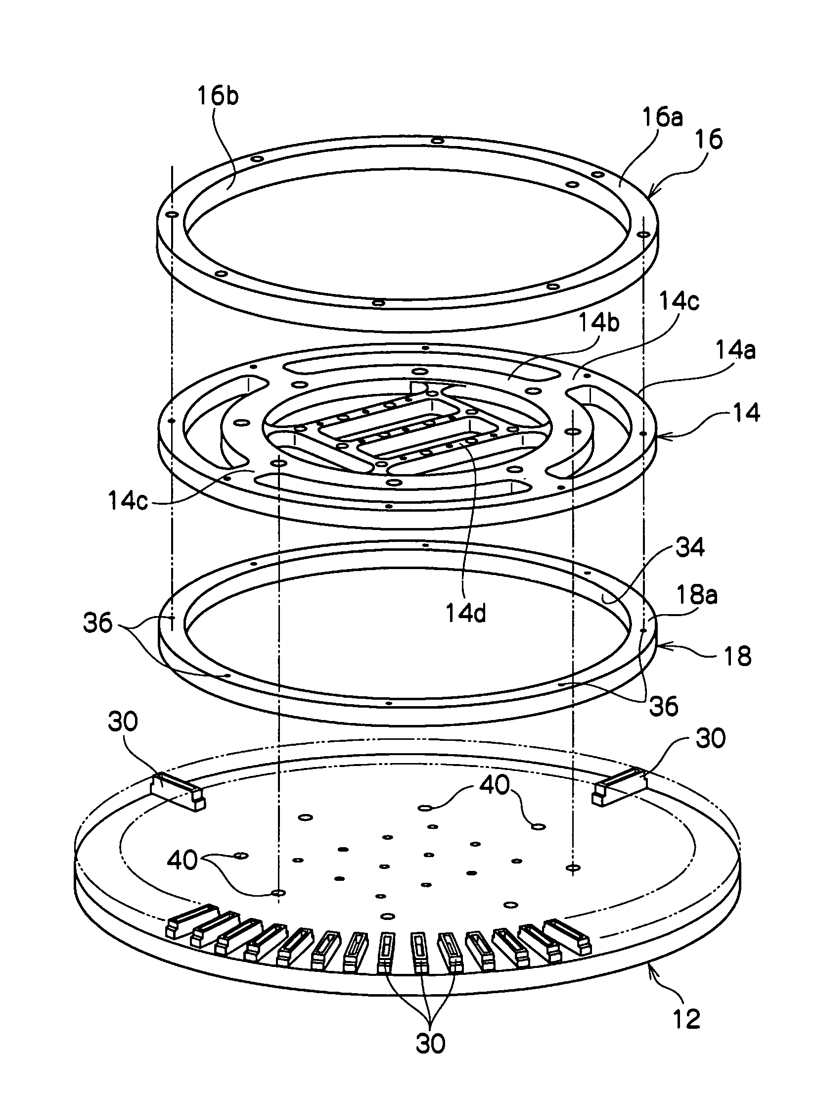
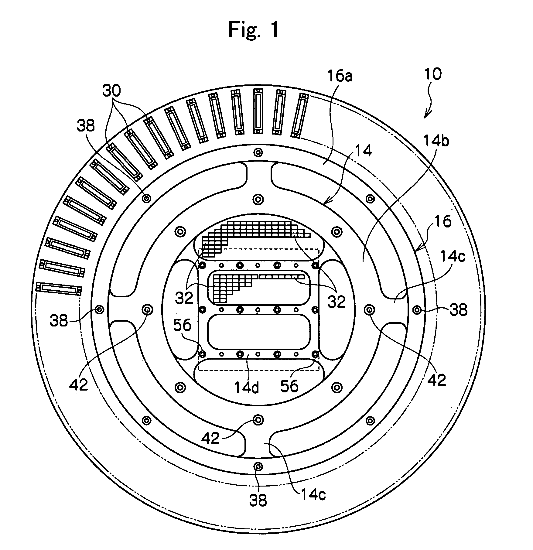
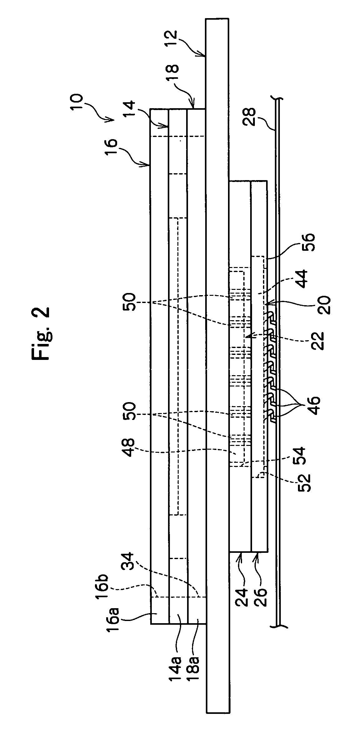
[0049]Referring to FIGS. 1 to 4, an electrical connecting apparatus 10 includes a circular flat-plate-shaped wiring board 12, an annular flat-plate-shaped reinforcing plate 14 attached to the center region on the upper surface of the wiring board 12 in a state of being spaced outward from the wiring board 14, an annular thermal deformation restriction member 16 attached to the upper surface of the reinforcing plate 12 to be piled thereon, an annular auxiliary member 18 arranged between the wiring board 12 and the reinforcing plate 14, a probe assembly 20 spaced downward from the lower surface of the wiring board 12, a flat-plate-shaped electrical connector 22 attached to the center on the lower surface of the wiring board 12, a base ring 24 housing the electrical connector 22, and a fixing ring 26 attaching the probe assembly 20 to the wiring board 12.

[0050]These parts 12 to 26 are integrally attached by plural screw members as described later and are used for connection between res...


PUM


Abstract

In an electrical connecting apparatus, a thermal deformation restriction member, a reinforcing plate, and an auxiliary member are made of materials having smaller thermal expansion coefficients in this order, and a wiring board supporting a probe assembly is coupled with the reinforcing plate. The auxiliary member has a void inside the coupling region with the reinforcing plate. The void receives the deformed part when the center portion of the wiring board is deformed toward the reinforcing plate. Thus, the thermal deformation restriction member, the reinforcing plate, and the auxiliary member function as a three-layer bimetal having a sandwich structure, and the thermal deformation of the wiring board is restricted effectively.

Description

TECHNICAL FIELD[0001]The present invention relates to an electrical connecting apparatus used for electrical connection between a device under test such as an integrated circuit to be tested and a tester for performing an electrical test of the device under test.BACKGROUND ART[0002]As one of the electrical connecting apparatuses of this kind such as a probe card, there is one in which a probe assembly wherein a plurality of contactors or probes are attached to the lower surface of a probe substrate is attached to the lower surface of a wiring board, and in which a reinforcing plate is attached to the upper surface of the wiring board (Patent Document 1).[0003]However, in the above conventional electrical connecting apparatus, when a device under test is tested under a high-temperature environment condition such as that in a burn-in test, the electrical connecting apparatus itself is exposed to the high temperature, and the electrical connecting apparatus, in particular, the wiring b...

Claims


Application Information

Patent Timeline
Patent Type & Authority Patents(United States)
IPC IPC(8): G01R31/02
CPCG01R31/2889G01R31/2874H01R33/76
Inventor MIURA, KIYOTOSHISATO, HITOSHI
Owner NIHON MICRONICS
Why Eureka
Try Eureka