
Linear groove and transition groove cutter device

A technology of bevel cutting and straight line transition, which is applied in the direction of auxiliary devices, welding/cutting auxiliary equipment, auxiliary welding equipment, etc., can solve the problems of inability to perform transition bevel cutting, etc., to improve cutting production efficiency, control thermal deformation, structure compact effect

Inactive Publication Date: 2014-03-26
NINGBO JINFENG WELDING & CUTTING MACHINERY MFR
View PDF4 Cites 0 Cited by
  • Summary
  • Abstract
  • Description
  • Claims
  • Application Information

AI Technical Summary

Problems solved by technology

[0003] In order to overcome the deficiency that the existing linear bevel cutting device cannot perform transitional bevel cutting, the present invention provides a linear transitional bevel cutting device that can complete the transitional bevel cutting while cutting the linear bevel of the plate

Method used


Image

  • Linear groove and transition groove cutter device
  • Linear groove and transition groove cutter device
  • Linear groove and transition groove cutter device

Examples


Embodiment Construction

[0017] The present invention will be described in further detail below in conjunction with the accompanying drawings and specific embodiments.

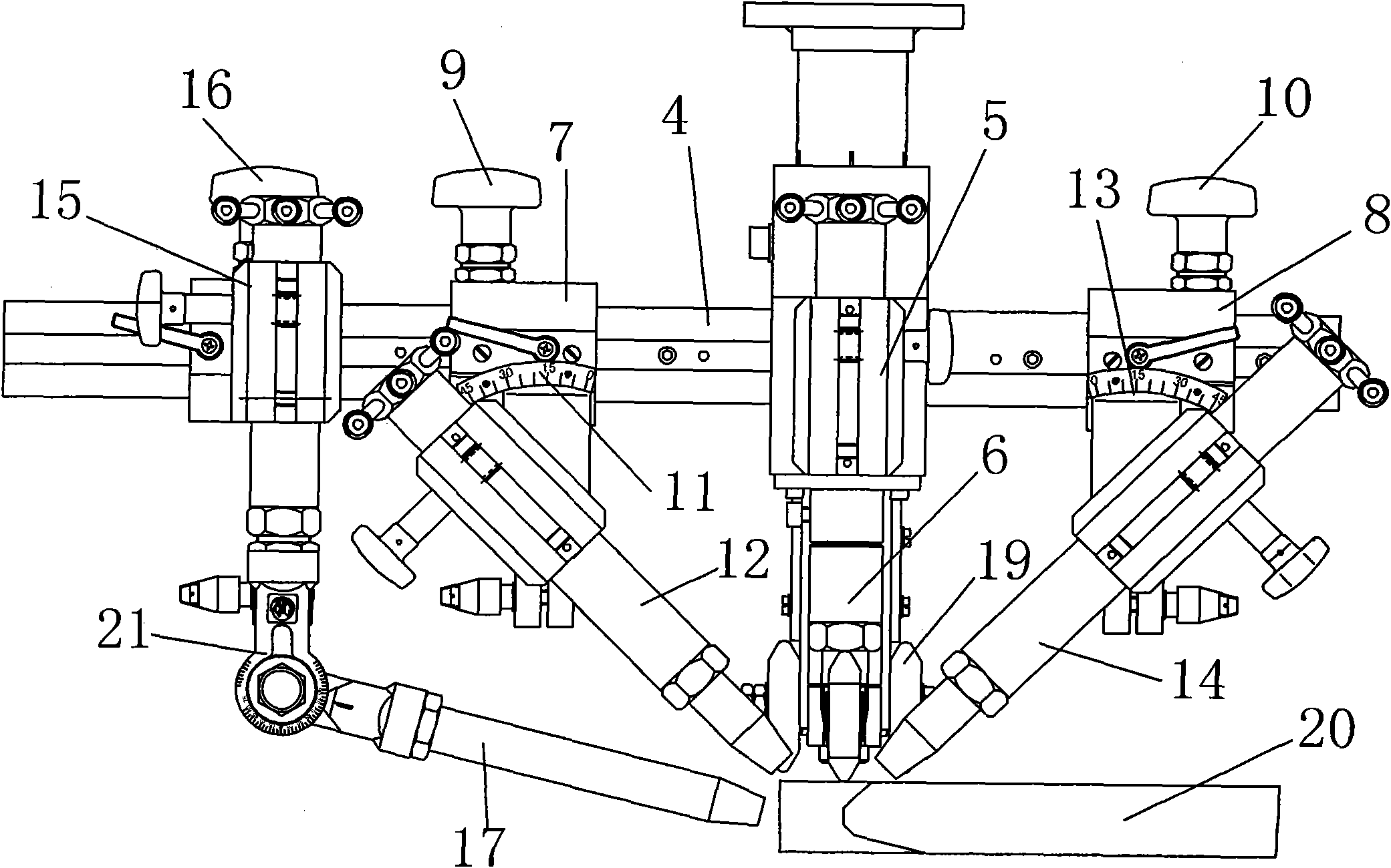
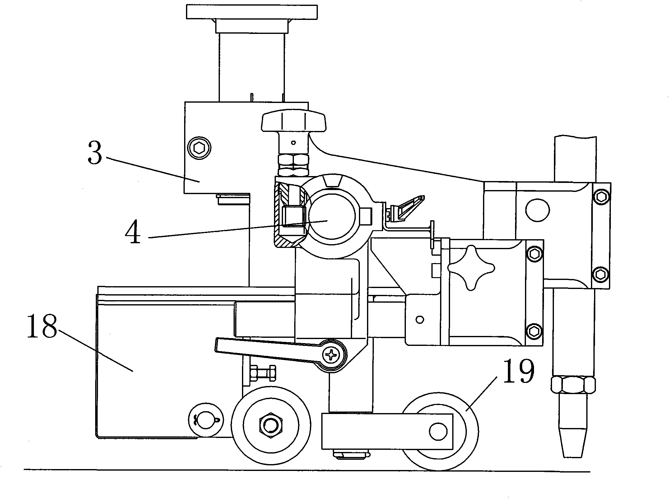
[0018] A linear transition bevel cutting device, comprising a frame 3, a rack bar 4 is provided on the frame 3, a central cutting torch connecting frame 5 is fixed on the rack bar 4, and the center A central cutting torch 6 is arranged on the cutting torch connecting frame 5;

[0019] Both sides of the central cutting torch connecting frame 5 have a left mobile body 7 and a right mobile body 8 respectively, the left mobile body 7 is connected with the left hand wheel 9, and the left hand wheel 8 is connected with the rack bar 4 meshing; the right moving body 8 is connected with the right hand wheel 10, and the right hand wheel 10 is meshed with the rack bar 4;

[0020] The left moving body 7 is provided with a left cutting torch holder 11, and the left cutting torch holder 11 is provided with a left cutting torch 12; the right moving...


PUM


Abstract

The invention discloses a linear groove and transition groove cutter device comprising a stand, wherein the stand is provided with a rack rod fixedly provided with a center cutting torch link span; two sides of the center cutting torch link span are respectively provided with a left moving body and a right moving body, wherein the left moving body is connected with a left handwheel meshed with the rack rod; the right moving body is connected with the right handwheel meshed with the rack rod; and the left moving body is provided with a left cutting torch clamp holder, and the right moving body is provided with a right cutting torch clamp holder. The linear groove and transition groove cutter device also comprises a transition moving body connected with a transition handwheel meshed with the rack rod; and the transition moving body is provided with a transition cutting torch clamp holder provided with a transition cutting torch. The whole cutter device has the advantages of compact structure and convenience for operation. The device can simultaneously cut a linear groove and a transition groove, thereby greatly improving cutting production efficiency, and lowering labor intensity. In addition, the cutting precision and the surface quality of workpieces are high, which can satisfy the process requirements of automatic welding, without subsequent processing.

Description

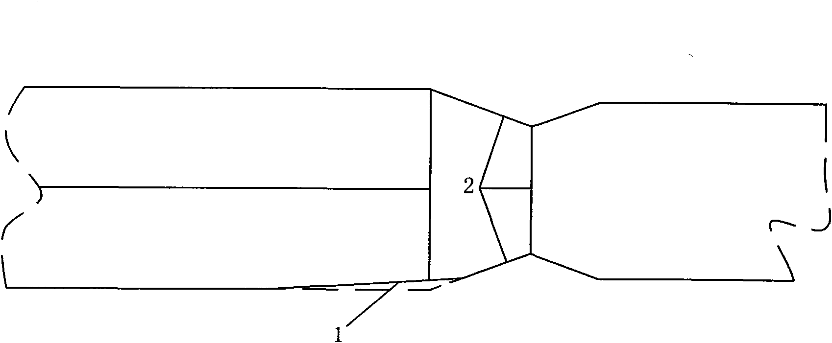
(1) Technical field [0001] The invention relates to a linear transition bevel cutting device. (2) Background technology [0002] Such as figure 1 As shown, in order to reduce the weight of structural parts and improve the strength of structural parts in shipbuilding, bridge building, construction and other industries, it is often necessary to splice plates of different thicknesses together, which will cause welding stress concentration at the weld due to the different thickness of the plates , it is easy to cause fatigue failure of structural members. Therefore, it is necessary to cut a transition groove 1 on the thick plate before welding, so that the thickness of the thicker workpiece at the weld is the same as that of the thinner workpiece. The current processing method is to use a cutting machine to complete the linear groove 2, and then use manual and semi-automatic trolleys to process the transition groove 1 of the workpiece, which not only has low production efficie...

Claims


Application Information

Patent Timeline
Patent Type & Authority Patents(China)
IPC IPC(8): B23K37/00
Inventor 章德均李乃健
Owner NINGBO JINFENG WELDING & CUTTING MACHINERY MFR
Learn More