
Flywheel and clutch lift
a technology of clutches and flywheels, which is applied in the direction of lifting devices, mobile jacks, vehicles with pivoted arms, etc., can solve the problems of difficult installation and de-installation of clutches, particularly those incorporated in large truck engines, and achieve the effect of convenient and convenient us
- Summary
- Abstract
- Description
- Claims
- Application Information
AI Technical Summary
Benefits of technology
Problems solved by technology
Method used
Image

Examples
Embodiment Construction
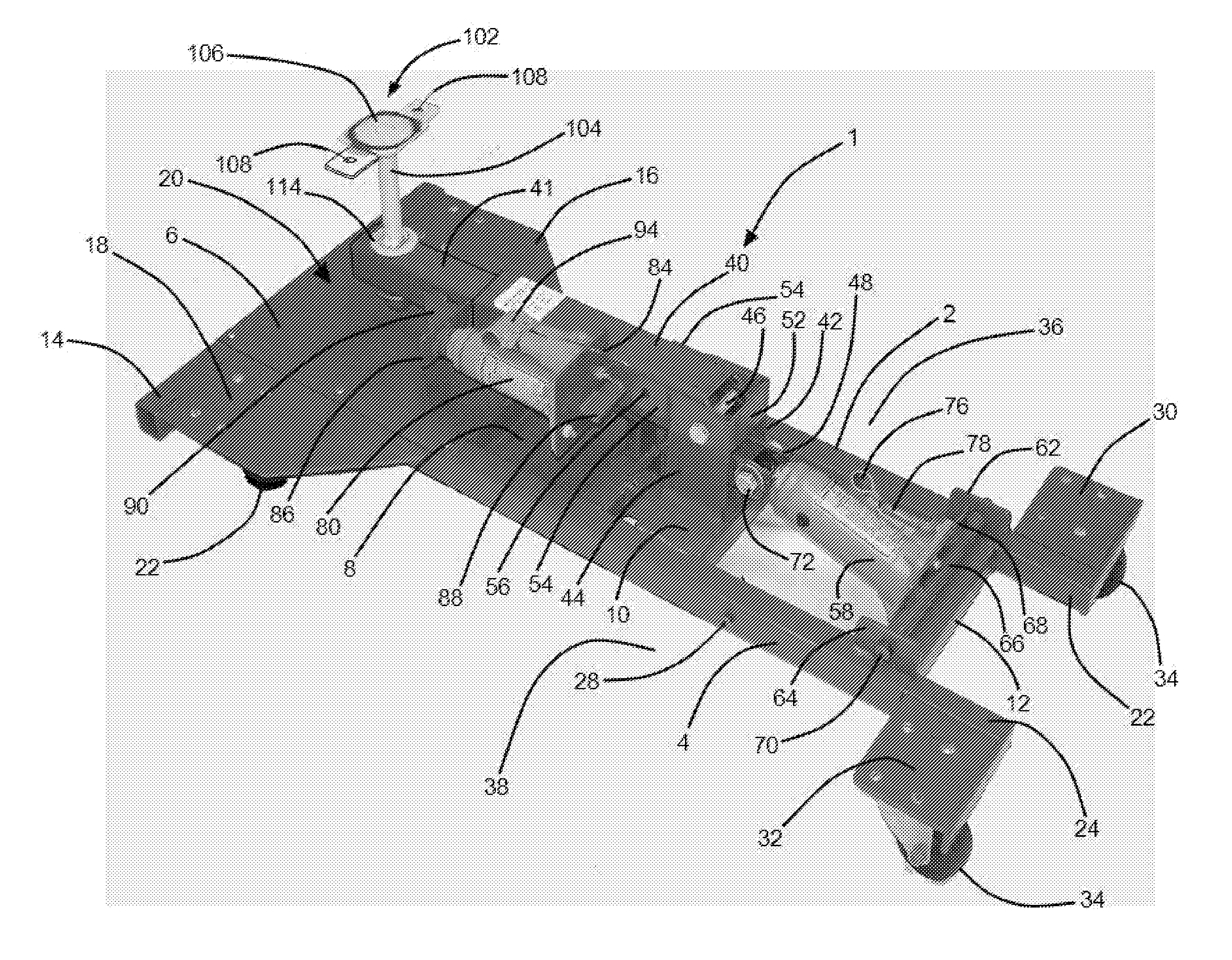
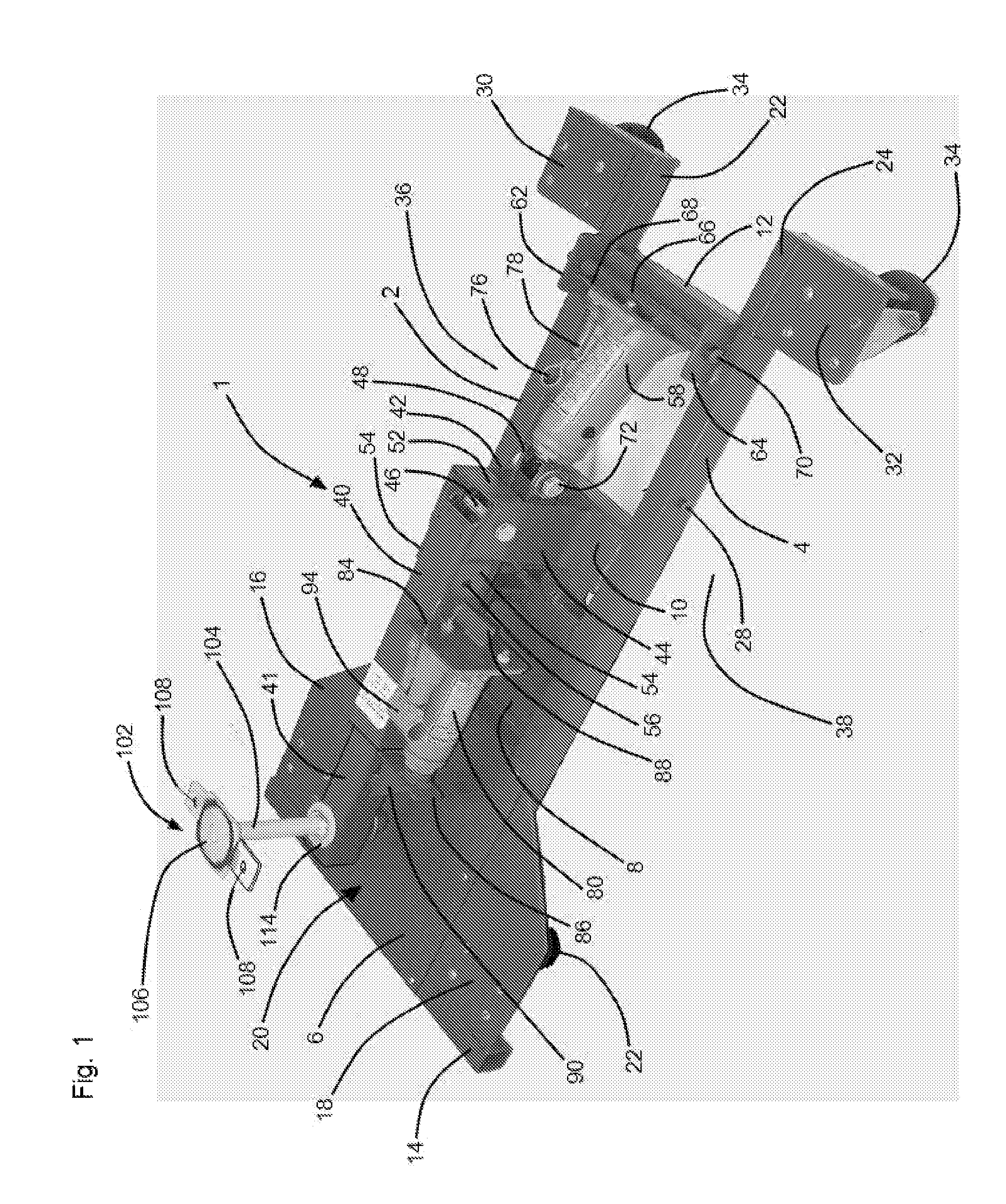
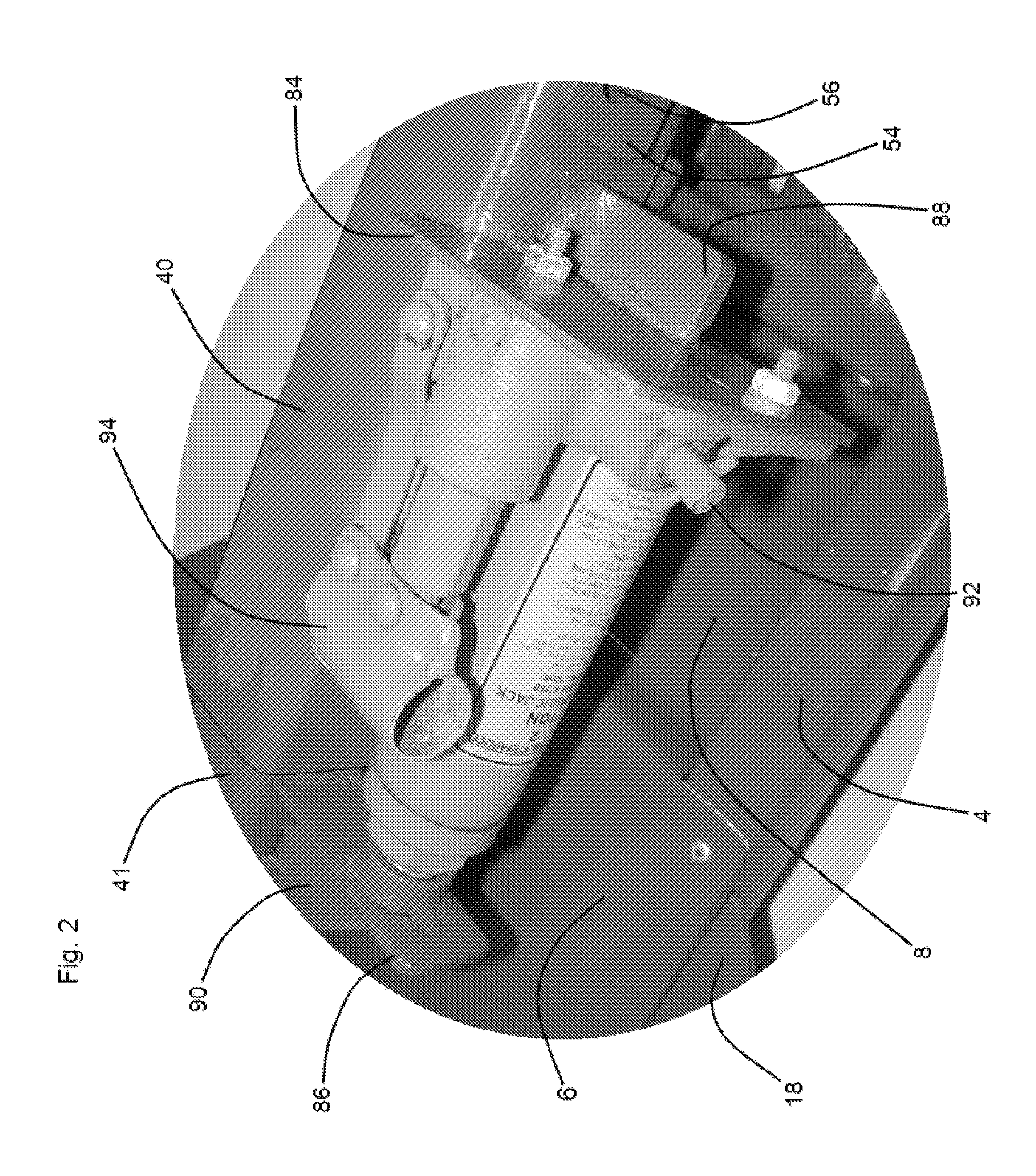
[0024]Referring now to the drawings, and in particular to FIG. 1, a preferred embodiment of the instant inventive flywheel and clutch lift is referred to generally by Reference Arrow 1. The base or foundational structure of the flywheel and clutch lift 1 preferably comprises a mechanic's sitting position floor creeper which preferably comprises left and right chassis beams 2 and 4. Each of the left and right chassis beams 2 and 4 preferably comprises hollow bored steel square tubing. The left and right chassis beam components 2 and 4 of the mechanic's floor creeper base of the instant inventive lift, are preferably rigidly laterally interconnected by a series of cross members 6, 8, 10, and 12. The rearmost cross member 6 is preferably configured to function as a seat plate, and the cross member 8 immediately forward of such rearmost cross member 6 is preferably configured as an upwardly opening “C” channel for advantageous service as a parts and tool tray. A “T” bar 14 is preferably...
PUM
 Abstract
Description
Claims
Application Information