Intervertebral implant

a technology of intervertebral implants and implants, which is applied in the field of medical devices, can solve the problems of high cost, inconvenient operation, and injury to the vertebrae and associated connective elements, and achieve the effect of facilitating selective relative movemen

Active Publication Date: 2012-01-31
DEPUY SYNTHES PROD INC
View PDF121 Cites 524 Cited by
  • Summary
  • Abstract
  • Description
  • Claims
  • Application Information

AI Technical Summary

Benefits of technology

[0014]Accordingly, one embodiment of the present invention comprises a spinal fusion intervertebral implant that includes upper and lower body portions and an actuator shaft that can be sized and configured to be received therebetween. The upper and lower body portions can each have proximal surfaces disposed at proximal ends thereof. The actuator shaft can comprise an inner member and an outer sleeve member adapted to be translatable relative to the inner member. The inner member can have distal and proximal ends and at least one retention structure disposed therebetween. The outer sleeve member can have a proximal end and at least one complementary retention structure being sized and configured to engage the retention structure of the inner member to facilitate selective relative movement of the proximal end of the outer sleeve member toward the distal end of the inner member without rotation.
[0016]In accordance with another embodiment, a spinal fusion intervertebral implant is provided that comprises upper and lower body portions each having proximal and distal surfaces at proximal and distal ends thereof. The proximal and distal surfaces of the upper and lower body portions can be configured to generally face each other. The implant can further comprise an actuator shaft received between the upper and lower body portions. The actuator shaft can comprise an inner member and an outer sleeve member selectively moveable relative to the inner member. The implant can further comprise a distal wedge member disposed at a distal end of the inner member. The distal wedge member can have an engagement surface configured to provide ratchet-type engagement with the distal surfaces of the upper and lower body portions upon selective relative movement of the distal end of the inner member toward the proximal end of the outer sleeve member. Further, the implant can comprise a proximal wedge member disposed at a proximal end of the outer sleeve member. The proximal wedge member can have an engagement surface configured to provide ratchet-type engagement with the proximal surfaces of the upper and lower body portions upon selective relative movement of the proximal end of the outer sleeve member toward the distal end of the inner member. In such an embodiment, longitudinal movement of the distal wedge member against the distal surfaces and the longitudinal movement of the proximal wedge member against the proximal surfaces can cause separation of the upper and lower body portions. Furthermore, the ratchet-type engagement between the distal and proximal wedge members and the respective ones of the proximal and distal surfaces of the upper and lower body portions can maintain separation of the upper and lower body portions.
[0017]In accordance with yet another embodiment, a method of implanting a implant is also provided. The method can comprise the steps of positioning the implant between two vertebral bodies and moving an inner member of an actuator shaft of the implant in an proximal direction relative to an outer sleeve member disposed about the inner sleeve member to force a proximal protrusion of the outer sleeve member against proximal surfaces of respective ones of upper and lower body portions of the implant to separate the upper and lower body portions to cause the implant to expand intermediate the vertebral bodies.
[0018]In accordance with yet another embodiment, a method of implanting a implant is also provided. The method can comprise the steps of positioning the implant between two vertebral bodies and rotating a screw mechanism of the implant to cause proximal and distal wedge members to converge toward each other and engage respective ones of proximal and distal surfaces of upper and lower body portions of the implant to separate the upper and lower body portions to cause the implant to expand.

Problems solved by technology

Additionally, the vertebrae and associated connective elements are subject to injuries, including fractures and torn ligaments and surgical manipulations, including laminectomies.
Furthermore, notwithstanding the variety of efforts in the prior art described above, these intervertebral implants and techniques are associated with another disadvantage.
In particular, these techniques typically involve an open surgical procedure, which results higher cost, lengthy in-patient hospital stays and the pain associated with open procedures.

Method used


Image

  • Intervertebral implant
  • Intervertebral implant
  • Intervertebral implant

Examples


Embodiment Construction

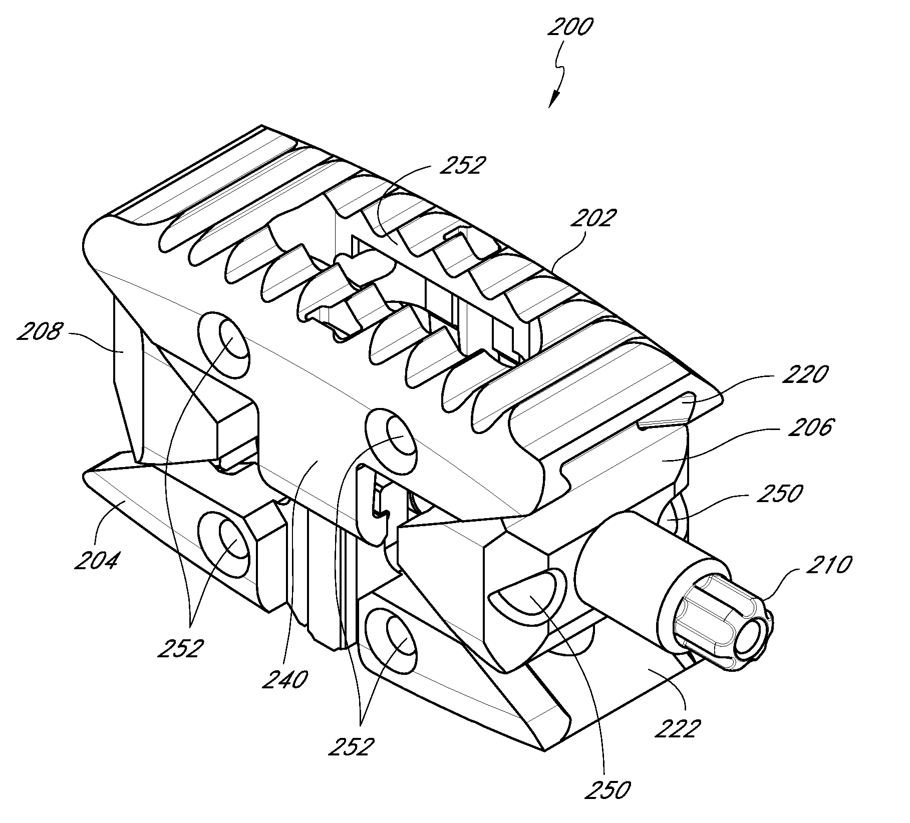
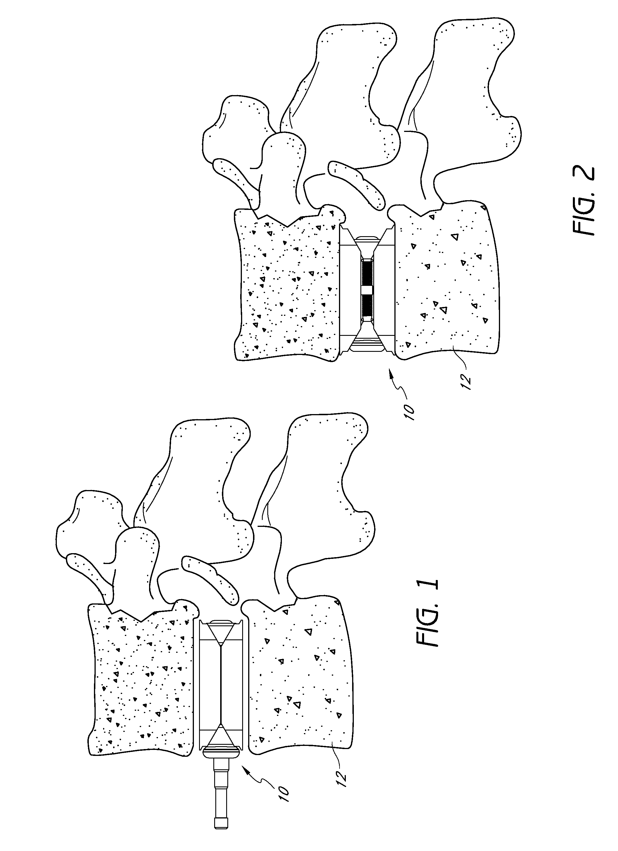
[0067]In accordance with certain embodiments disclosed herein, an improved intervertebral implant is provided that allows the clinician to insert the intervertebral implant through a minimally invasive procedure. For example, in one embodiment, one or more intervertebral implants can be inserted percutaneously to reduce trauma to the patient and thereby enhance recovery and improve overall results of the surgery.

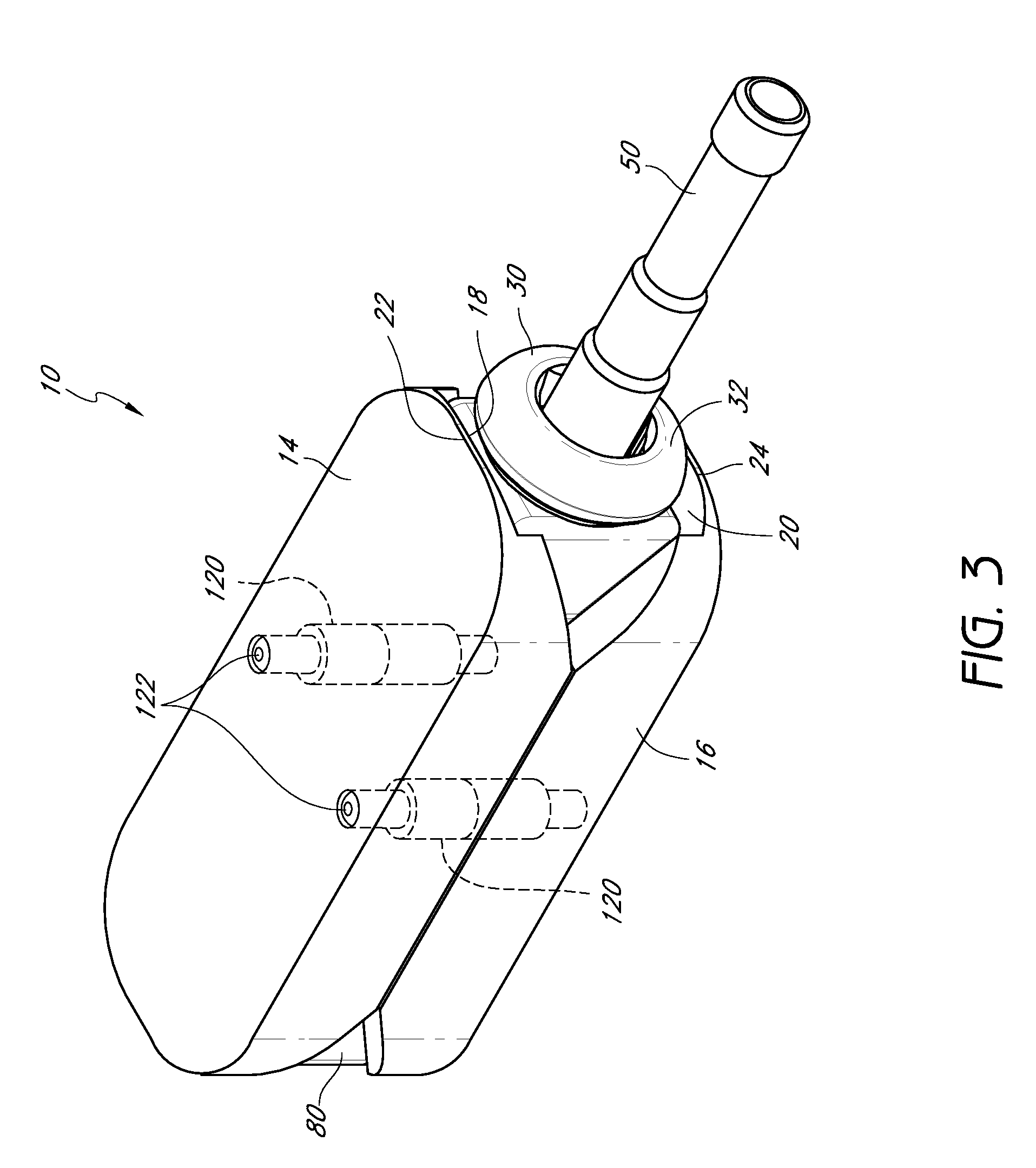
[0068]For example, in one embodiment, an intervertebral implant includes a plurality of body sections that are selectively separable and expandable upon contraction of a centrally disposed actuator. The actuator can be utilized to contract against faces of the body sections to cause the expansion thereof. The implant can also be configured such that the actuator provides for both the expansion and contraction of the body sections. The actuator can comprise an interaction between the body sections and another element, an action performed by another element, or a combination o...


PUM

PropertyMeasurementUnit
heightaaaaaaaaaa
widthaaaaaaaaaa
lengthaaaaaaaaaa

Abstract

An adjustable spinal fusion intervertebral implant is provided that can comprise upper and lower body portions that can each have proximal and distal wedge surfaces disposed at proximal and distal ends thereof. An actuator shaft disposed intermediate the upper and lower body portions can be actuated to cause proximal and distal protrusions to converge towards each other and contact the respective ones of the proximal and distal wedge surfaces. Such contact can thereby transfer the longitudinal movement of the proximal and distal protrusions against the proximal and distal wedge surfaces to cause the separation of the upper and lower body portions, thereby expanding the intervertebral implant. The upper and lower body portions can have side portions that help facilitate linear translational movement of the upper body portion relative to the lower body portion.

Description

PRIORITY INFORMATION[0001]The present application is a nonprovisional application of U.S. Provisional Application Ser. No. 60 / 869,088, filed Dec. 7, 2006, the entirety of the disclosure of which is hereby incorporated by reference.BACKGROUND[0002]1. Field of the Invention[0003]The present invention relates to medical devices and, more particularly, to an intervertebral implant.[0004]2. Description of the Related Art[0005]The human spine is a flexible weight bearing column formed from a plurality of bones called vertebrae. There are thirty three vertebrae, which can be grouped into one of five regions (cervical, thoracic, lumbar, sacral, and coccygeal). Moving down the spine, there are generally seven cervical vertebra, twelve thoracic vertebra, five lumbar vertebra, five sacral vertebra, and four coccygeal vertebra. The vertebra of the cervical, thoracic, and lumbar regions of the spine are typically separate throughout the life of an individual. In contrast, the vertebra of the sac...

Claims


Application Information

Patent Timeline
Patent Type & Authority Patents(United States)
IPC IPC(8): A61F2/44
CPCA61F2/447A61F2/4611A61F2/4455A61B2017/0256A61F2002/30062A61F2002/30507A61F2002/30522A61F2002/30523A61F2002/30551A61F2002/30579A61F2002/30677A61F2002/30892A61F2002/4475A61F2002/448A61F2002/4629A61F2002/4667A61F2210/0004A61F2220/0025A61F2310/00017A61F2310/00023A61F2002/30092A61F2002/3055A61F2002/30593A01H5/12A24B13/00A24B15/18A24D1/00A24F47/00Y02E50/10A61F2/46A61B17/025A61F2/30771A61F2/4657A61F2002/4659A61F2002/30387A61F2002/30785A61F2002/4661
Inventor OLMOS, FAUSTOCULBERT, BRADFLOWER, BOB
Owner DEPUY SYNTHES PROD INC
Why Eureka
Try Eureka