Accessory module with integrated electronic devices

an electronic device and accessory module technology, applied in the field of optical device mounting, can solve the problems of occupying valuable space, not enough space on the upper receiver to accommodate all, and many military personnel have multiple sighting devices, so as to reduce the amount of space required for mounting and reducing the amount of space required

Inactive Publication Date: 2012-04-17
SWAN RICHARD E
View PDF33 Cites 34 Cited by
  • Summary
  • Abstract
  • Description
  • Claims
  • Application Information

AI Technical Summary

Benefits of technology

[0012]It is therefore an object of the present invention to provide an optical accessory module that provides for the integration of several different accessories into a single location on the rail system thus reducing the amount of space required for mounting them onto the weapon. It is a further object of the present invention to provide an accessory module that provides for the integration of several different accessories into a device that is received at a location between a weapon accessory (optical sighting device) and the mounting interface for the weapon accessory such that the entire assembly occupies a single position on the rail system thus reducing the amount of space required for collectively mounting them onto the weapon.

Problems solved by technology

The difficulty is that many military personnel have multiple sighting devices, in addition to a variety of lighting devices, accessory handgrips, etc. that could also be attached to the weapon for enhanced use of the weapon.
In view of the broad range of add on accessories, there is often not enough space on the upper receiver to accommodate all of the accessories that the user may desire to use.
Often, since one of the accessories used on the upper rail is an optical sight, most other accessories end up blocking the sight when mounted on the upper rail.
Further, each of these additional accessories also takes up valuable space on the available dovetail rails and limits the overall number of possible accessories that can be mounted thereto.
As a result, soldiers often have to make choices about which types of accessories they will mount for particular missions because all of the desired accessories will simply not fit onto the available rail space on the weapon.

Method used


Image

  • Accessory module with integrated electronic devices
  • Accessory module with integrated electronic devices
  • Accessory module with integrated electronic devices

Examples


Embodiment Construction

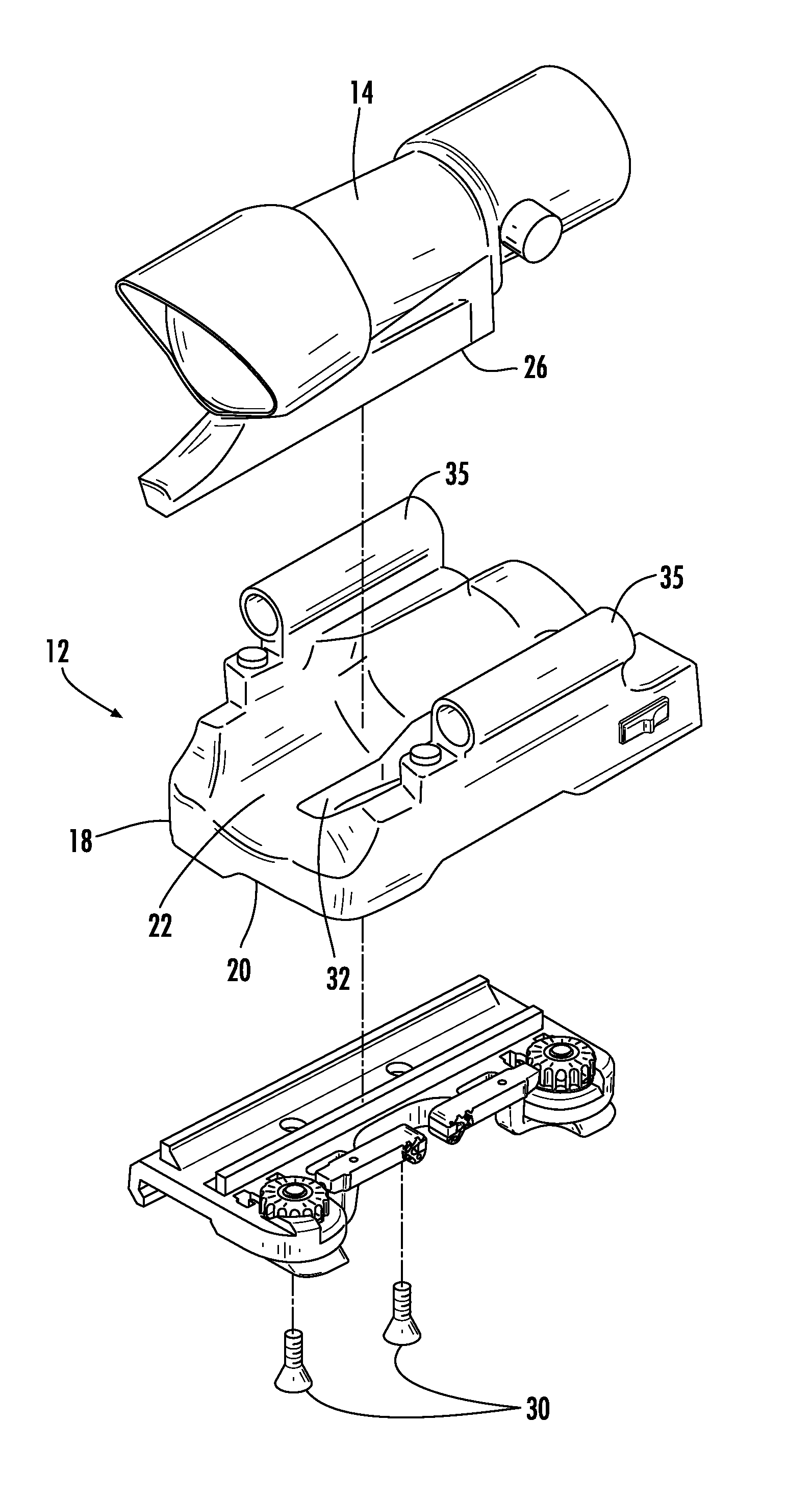
[0025]Now referring to the drawings, the accessory module is shown and generally illustrated in the figures. As can be seen, the accessory module of the present invention is generally configured to positioned between an optical sight (also generally identified as a weapon accessory) and a mounting interface as are traditionally employed combat firearms in a manner that allows various accessories to be positioned such that they do not interfere with the operation of other rail mounted accessories and so that they do not occupy any additional rail mounting space.

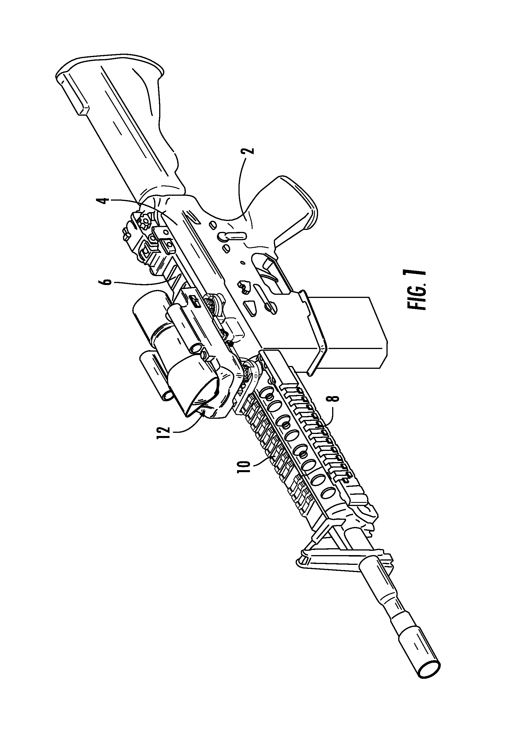
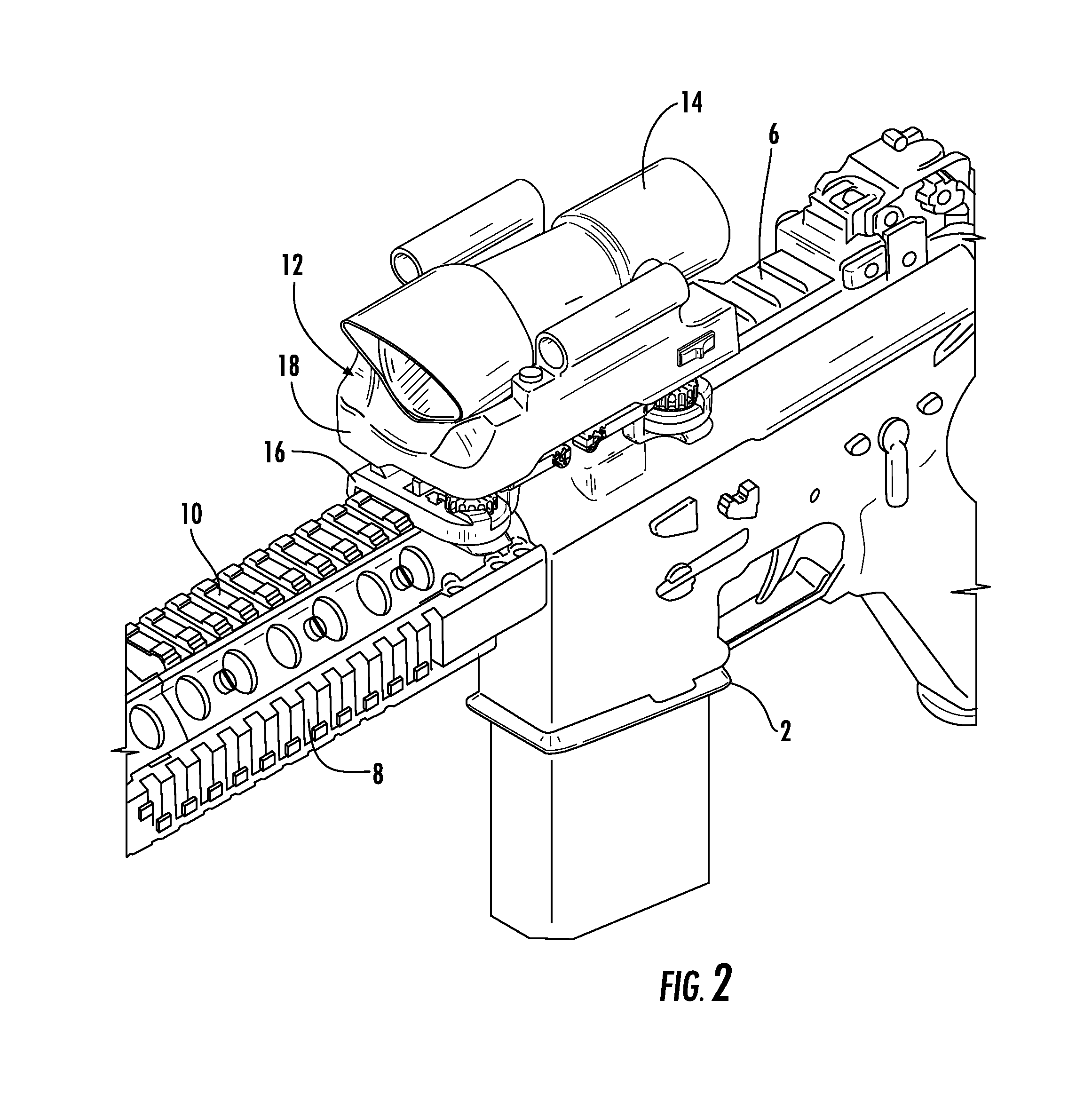
[0026]Turning now to FIGS. 1-2, a combat firearm 2 is depicted here in the form of an M4 carbine such as the type employed by the US military. The firearm 2 includes an upper receiver 4 with a dovetail rail 6 that extends along its upper surface. Further a hand guard assembly 8 can be seen extending from the front of the upper receiver 4 to the front sight of the firearm 2. The hand guard assembly 8 can also be seen to include...


PUM


Abstract

An accessory module is installed between a weapon accessory (optical sighting device) and its corresponding mounting interface. The accessory module includes a body having a lower surface which is configured and arranged to mate with the corresponding upper surface of the mounting interface and an upper surface that includes a seat that is configured and arranged to conform to and receive the outer surface of the weapon accessory. The accessory module includes electronic accessories, such as for example, a flashlight configured to emit visible white light, colored light and / or infrared light. Further, the accessory module may include laser devices therein such as a laser sight, an infrared laser for night vision targeting, or a laser range finder device. The accessory module may also be configured to include a taser and / or a compact video camera.

Description

CROSS-REFERENCE TO RELATED APPLICATIONS[0001]This application is related to and claims priority from earlier filed U.S. Provisional Patent Application No. 61 / 144,472, filed Jan. 14, 2009.BACKGROUND OF THE INVENTION[0002]The present invention relates generally to optical device mounts for use in connection with firearms and assault weapons. More specifically, the present invention relates to an accessory module that is received between an optical device and a mounting interface, wherein the accessory module includes integrated electronics, such as visible lights, infrared emitters, laser sighting devices, range finders, etc.[0003]In the general field of combat and commercial weaponry, numerous add-on enhancements have become available for attachment to standard firearms thereby significantly upgrading the capability of the firearm. One area within the broad scope of available firearms that is of particular interest is the M16 / M4 weapon system typically utilized in military or combat ...

Claims


Application Information

Patent Timeline
Patent Type & Authority Patents(United States)
IPC IPC(8): F41A15/00
CPCF41G1/387F41G11/003
Inventor SWAN, RICHARD E.
Owner SWAN RICHARD E
Why Eureka
Try Eureka