Check patentability & draft patents in minutes with Patsnap Eureka AI!

Infrared heat lamp having vertical burning position

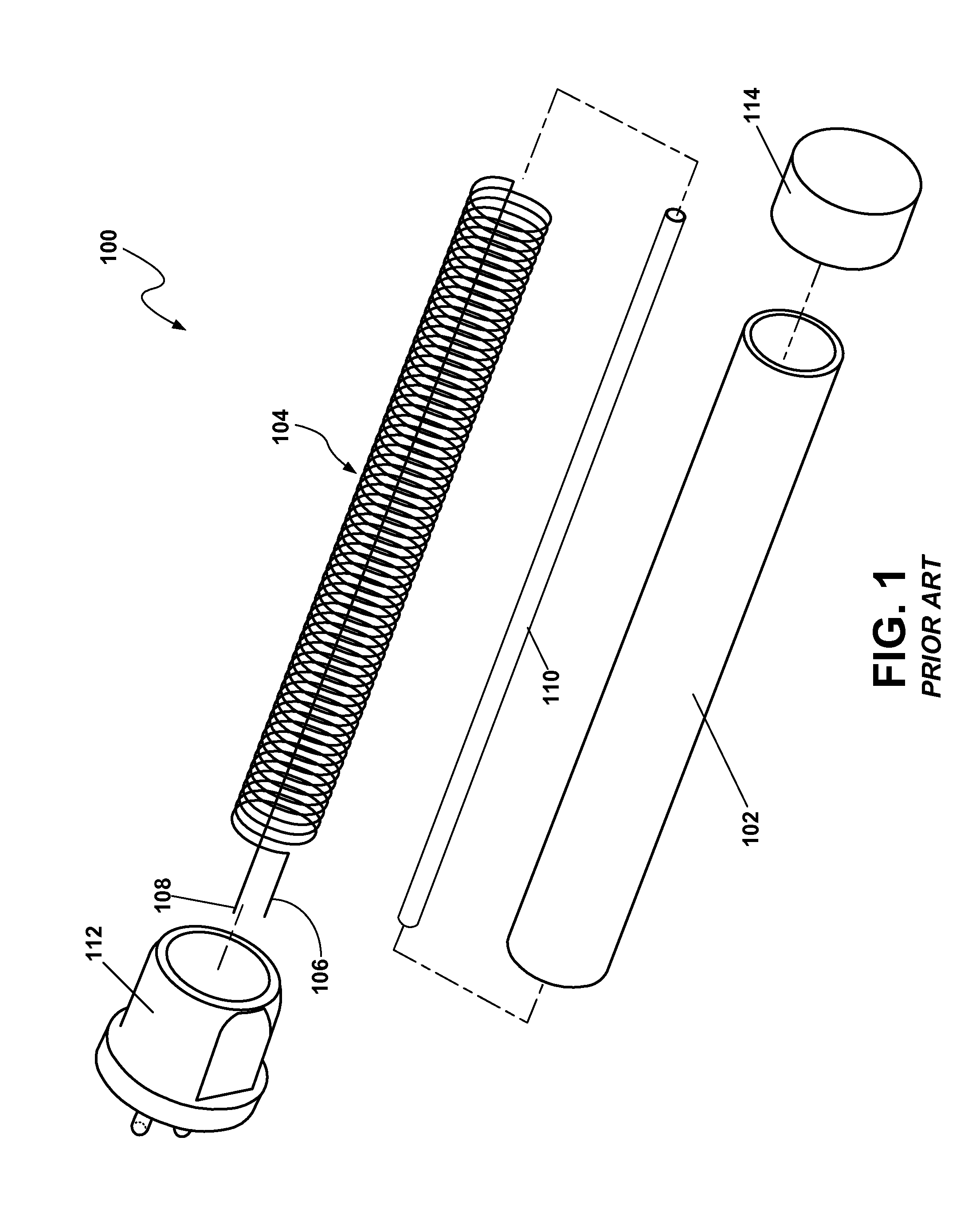
a heat lamp and vertical technology, applied in the field of infrared heat lamps, can solve the problems of limited horizontal or non-vertical operation restricting the positioning options of a heater system incorporating known heat lamps, and heating elements such as the coiled heating element 104 described above, etc., to achieve the effect of safe vertical operation

Active Publication Date: 2013-04-16
OSRAM SYLVANIA INC
View PDF9 Cites 0 Cited by
  • Summary
  • Abstract
  • Description
  • Claims
  • Application Information

AI Technical Summary

Benefits of technology

Enables the infrared heat lamp to operate safely and effectively in various orientations, including vertical, by preventing coil contact and short circuits, thus expanding positioning options and enhancing user flexibility.

Problems solved by technology

However, known heat lamps, such as the infrared heat lamp 100 described above, suffer the disadvantage of coil sagging and thus are limited to operation in horizontal or non-vertical orientations, thus restricting positioning options of a heater system incorporating known heat lamps.
In particular, heating elements, such as the coiled heating element 104 described above, may not safely operate in a vertical orientation, and, instead, may be limited to a horizontal burning position.
However, if in a vertical position, the sagging of the individual coils may lead to contact between one or more of the coils.
This can eventually cause a short circuit in the heating element, which leads to higher currents passing through the heating element with an associated increase in heating element temperature.
This increase in temperature further accelerates the coil sagging and causes a further compression of the turns of the coil, ultimately leading to damage of the heat lamp.

Method used


Image

  • Infrared heat lamp having vertical burning position
  • Infrared heat lamp having vertical burning position
  • Infrared heat lamp having vertical burning position

Examples


Embodiment Construction

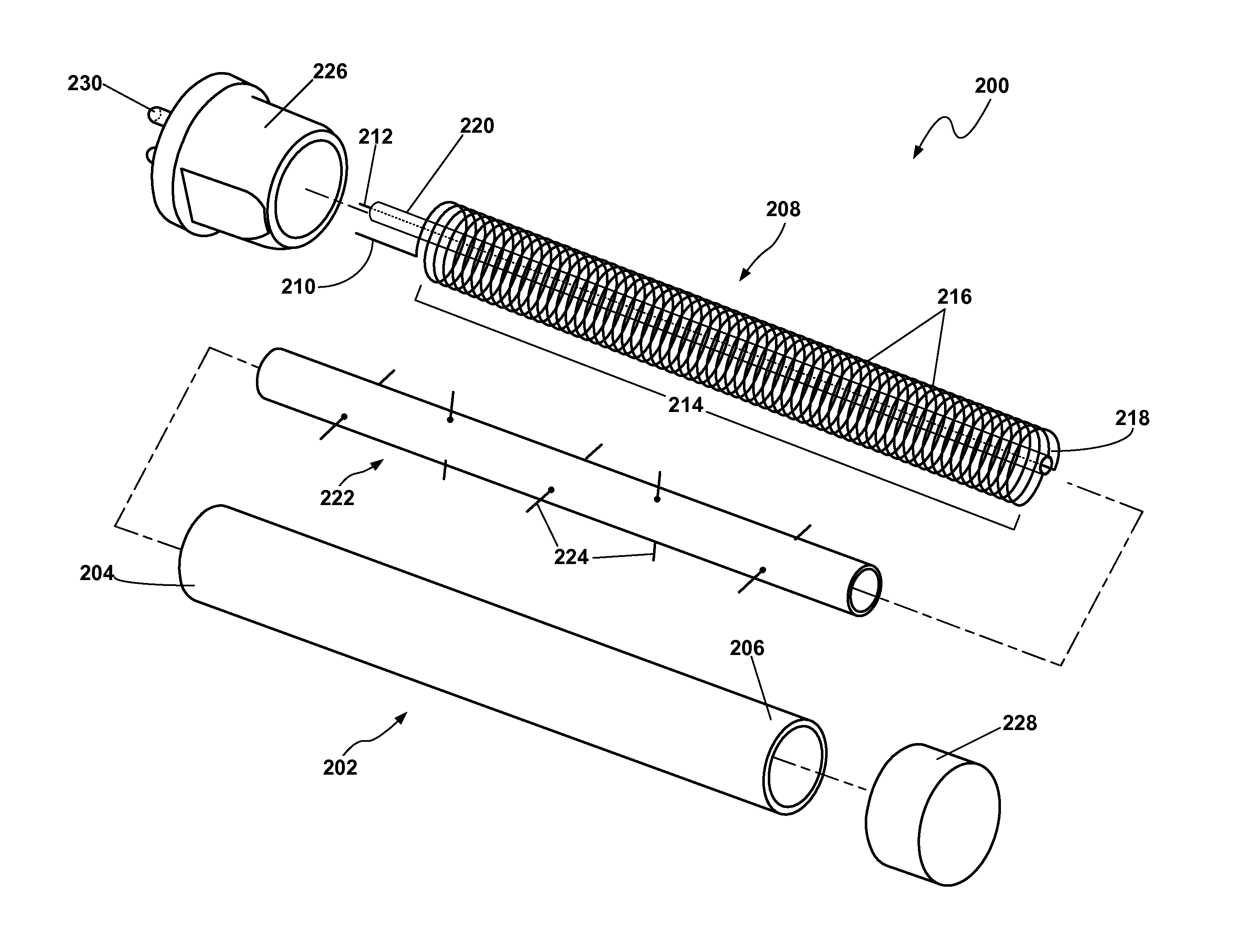
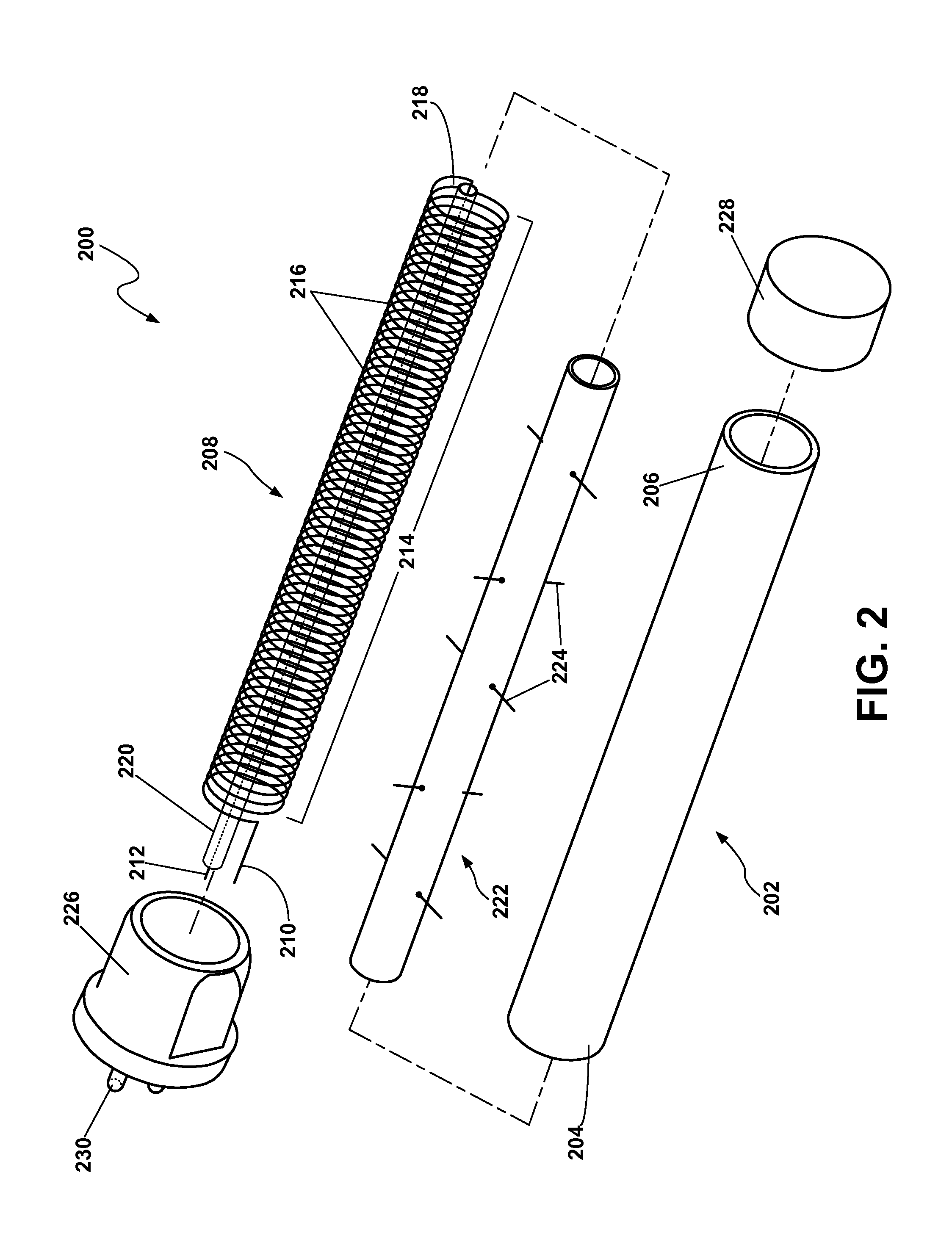
[0013]In general, this disclosure provides an infrared heat lamp configured to operate in a vertical burning position, as well as a horizontal burning position. The infrared heat lamp includes a coiled heating element disposed within an outer tubular member. The infrared heat lamp further includes an inner elongate member disposed within the coiled heating element, the inner elongate member having a plurality of support members extending therefrom and configured to engage and support the coiled heating element when the heat element is in a vertical orientation. An infrared heat lamp consistent with the present disclosure may be used in a compatible heater system and allows a user to position the heater system in a variety of desired orientations. In particular, an infrared heat lamp consistent with the present disclosure is configured to operate in a variety of burning positions, including, but not limited to, vertical and horizontal burning positions.

[0014]FIG. 2 is an exploded vie...


PUM


Abstract

An infrared heat lamp (200) having a vertical burning position includes an outer tubular member (202) and a heating element (208) having a coiled portion (214) at least partially disposed within the outer tubular member (202). The heating element (208) includes first and second terminal ends (210, 212), wherein the coiled portion (214) is defined therebetween, the coiled portion (214) having a plurality of turns (216) defining a through passage (218). The heat lamp (200) further includes an inner elongate member (222) disposed within the through passage (218) of the coiled portion (214), the inner elongate member (222) having a plurality of support members (224) extending therefrom. Each of the plurality of support members (224) engages at least one of the plurality of turns (216) of the coiled portion (214), whereby the coiled portion (214) is supported by the plurality of support members (224) when the heating element (208) is in a vertical orientation.

Description

FIELD[0001]The present disclosure relates generally to an infrared heat lamp, and, more particularly, to an infrared heat lamp configured operate in a vertical burning position.BACKGROUND[0002]Infrared heater systems may include infrared heat lamp(s) configured to emit infrared radiation, which, in turn, may be used as a deliberate heating source. For example, an infrared heater system may be used to cook and / or heat food and may also be used in industrial manufacturing processes, including, but not limited to curing of coatings, forming of plastics, annealing, plastic welding, and print drying. Additionally, an infrared heater system may be used to heat a surrounding environment, such as one's home or office.ACKNOWLEDGED PRIOR ART[0003]FIG. 1 is an exploded view of a prior art infrared heat lamp, such as one available in the United States from Osram Sylvania Inc. under the designation “J168” rated 500 W 115V and used in portable heaters marketed by EdenPURE®. The infrared heat lamp...

Claims


Application Information

Patent Timeline
Patent Type & Authority Patents(United States)
IPC IPC(8): H01K1/18H01K1/24H01K7/00
CPCH01K1/14H01K1/16H01K1/18H05B3/0038H05B3/0071
Inventor DE SANTIAGO, ARTURORODRIGUEZ, ANDRES
Owner OSRAM SYLVANIA INC
Features
  • R&D
  • Intellectual Property
  • Life Sciences
  • Materials
  • Tech Scout
  • Unparalleled Data Quality
  • Higher Quality Content
  • 60% Fewer Hallucinations
Learn More