Electronic detonator system

Active Publication Date: 2013-06-25
BATTELLE MEMORIAL INST
View PDF136 Cites 41 Cited by
  • Summary
  • Abstract
  • Description
  • Claims
  • Application Information

AI Technical Summary

Problems solved by technology

Rather, the initiating pellet comprises a high density, insensitive secondary explosive material that is positioned relative to the initiator such that functioning of the initiator causes detonation of the initiating pellet.

Method used


Image

  • Electronic detonator system
  • Electronic detonator system
  • Electronic detonator system

Examples


Embodiment Construction

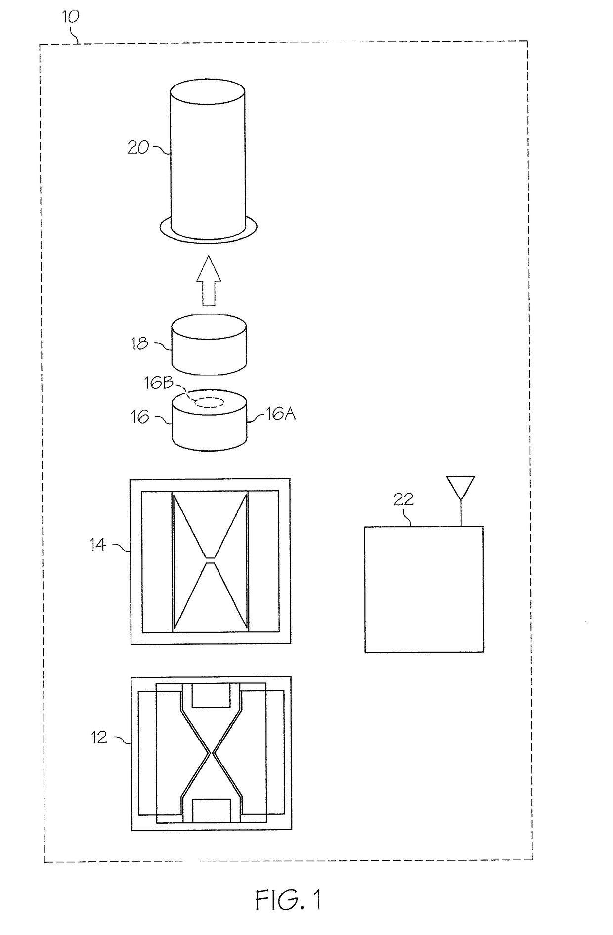
[0032]According to various aspects of the present invention, an electronic detonator includes in general, at least one high voltage switch and at least one initiator. The detonator further implements an actuation system having a trigger procedure that requires at least two trigger conditions that must be satisfied to initiate a detonation event in a corresponding explosive device. Particularly, the trigger procedure must be sufficient to actuate at least one high voltage switch, and the trigger procedure must be sufficient to actuate at least one initiator, in order to trigger the desired detonation event, as will be described in greater detail herein. Moreover, as will be described in greater detail herein, the detonator includes an integral fireset that provides the high voltage energy source(s) necessary to function both the high voltage switch(es) and the initiator(s) within the detonator.

[0033]Referring now to the drawings and in particular to FIG. 1, a detonator 10 is schemati...


PUM

PropertyMeasurementUnit
voltageaaaaaaaaaa
voltageaaaaaaaaaa
voltageaaaaaaaaaa

Abstract

A detonator includes a high voltage switch, an initiator and an initiating pellet. The detonator also includes a low voltage to high voltage firing set coupled to the switch and initiator such that the detonator includes a high voltage power source and initiator in an integrated package. The detonator may also include inductive powering and communications, a microprocessor, tracking and / or locating technologies, such as RFID, GPS, etc., and either a single or combination explosive output pellet. The combination explosive pellet has a first explosive having a first shock energy and a high brisance secondary explosive in the output pellet having a second shock energy greater than the shock energy of the first explosive. Systems are also provided for facilitating fast and easy deployment of one or more detonators in the field.

Description

CROSS REFERENCE TO RELATED APPLICATIONS[0001]This application is a continuation of International Application No. PCT / US2009 / 061961, filed Oct. 23, 2009, entitled “ELECTRONIC DETONATOR SYSTEM”, which claims the benefit of U.S. Provisional Patent Application Ser. No. 61 / 108,277, filed Oct. 24, 2008, entitled “ELECTRONIC DETONATOR SYSTEM”, the disclosures of which are hereby incorporated by reference.BACKGROUND[0002]The present invention relates in general to detonators, and in particular, to electronic detonators that integrate a high voltage switch, an initiator and a fireset.[0003]In various industries, such as mining, construction and other earth moving operations, it is common practice to utilize detonators to initiate explosives loaded into drilled blastholes for the purpose of breaking rock. In this regard, commercial electric and electronic detonators are conventionally implemented as hot wire igniters that include a fuse head as the initiating mechanism to initiate a correspon...

Claims


Application Information

Patent Timeline
Patent Type & Authority Patents(United States)
IPC IPC(8): C06C5/06
CPCF42B3/121F42D1/055F42B3/10F42B3/12F42D3/04F42B3/13F42B3/18F42D3/02F42D3/00
Inventor GIVENS, RICHARD W.LOESER, RONALD L.BACKHUS, ROGER F.
Owner BATTELLE MEMORIAL INST
Why Eureka
Try Eureka