Image forming apparatus, power supplying method, and recording medium
- Summary
- Abstract
- Description
- Claims
- Application Information
AI Technical Summary
Benefits of technology
Problems solved by technology
Method used
Image

Examples
Embodiment Construction
[0023]A description is given below, with reference to the FIG. 1 through FIG. 10 of embodiments of the present invention.
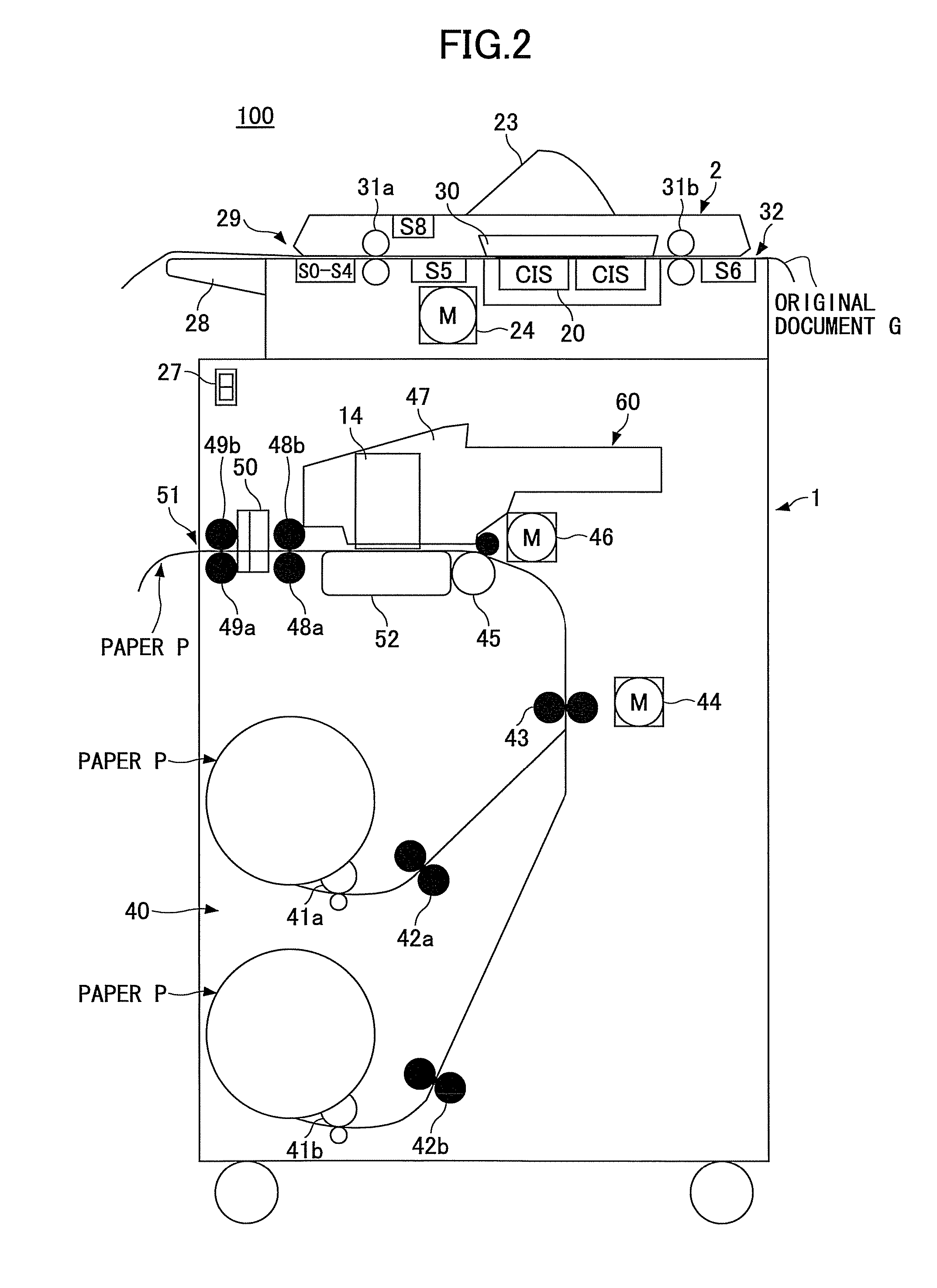
[0024]Reference symbols typically designate as follows:[0025]1: Plotter device;[0026]2: Scanner device;[0027]12: System control unit;[0028]14: Head;[0029]20: CIS(Contact sensor);[0030]21: First reading image processing unit;[0031]22: Second reading image processing unit;[0032]23: Operations unit;[0033]24: Original document feed motor;[0034]25: Scanner sensor;[0035]26,27: Power source switching unit;[0036]28: Original document supporter;[0037]30: Original document pressure plate;[0038]40: Paper feeding unit;[0039]41a,41b,42a,42b,43: Paper ejecting roller;[0040]46: Resisting motor;[0041]47: Carriage;[0042]48a,48b,49a,49b: Paper ejecting roller;[0043]50: Cutter;[0044]60: Image forming unit;[0045]70: Reading unit; and[0046]100: Image forming apparatus.
[0047]A terminology of “original document” (manuscript) may include a handwritten original document, printed original ...
PUM
 Abstract
Description
Claims
Application Information
 - R&D
- Intellectual Property
- Life Sciences
- Materials
- Tech Scout
- Unparalleled Data Quality
- Higher Quality Content
- 60% Fewer Hallucinations
Browse by: Latest US Patents, China's latest patents, Technical Efficacy Thesaurus, Application Domain, Technology Topic, Popular Technical Reports.
© 2025 PatSnap. All rights reserved.Legal|Privacy policy|Modern Slavery Act Transparency Statement|Sitemap|About US| Contact US: help@patsnap.com