System and method for generating electricity

a technology of electricity generation and system, applied in the direction of electric generator control, machines/engines, mechanical apparatus, etc., can solve the problems of insufficient hydroelectric power generation, inability to meet the needs of small towns and municipalities, and insufficient infrastructure to generate hydroelectric power, etc., to achieve the effect of low operating cost, small amount of electric power, and convenient us

Inactive Publication Date: 2013-10-22
HUEBNER ROBERT L
View PDF55 Cites 25 Cited by
  • Summary
  • Abstract
  • Description
  • Claims
  • Application Information

AI Technical Summary

Benefits of technology

[0006]The present invention addresses these problems by providing a relatively inexpensive hydroelectric power generator that may be easily set up and utilized on the bank of a stream or river, and is operable to generate relatively small amounts of electric power sufficient for use by small towns and municipalities. Because the invention utilizes a natural, freely available, and generally continuous power source, the operating costs of the present invention are very low, generally requiring only the initial investment for the generator itself as well as minimal upkeep.

Problems solved by technology

However, such infrastructure is necessarily expensive and time consuming to build and set up.
Further, such hydroelectric power plants must be run by trained and dedicated engineers and other professionals, making the cost of generating hydroelectric power simply out of the reach of most smaller towns and municipalities.
Thus, what has been lacking in the field of hydroelectric power is the ability to inexpensively and efficiently generate electric power on a smaller, more economic scale wherein smaller towns and municipalities located near large flowing bodies of water may generate electric power for personal consumption and may also sell excess power to larger power grids and networks.

Method used


Image

  • System and method for generating electricity
  • System and method for generating electricity
  • System and method for generating electricity

Examples


Embodiment Construction

[0019]The following description is presented to enable any person skilled in the art to make and use the invention, and is provided in the context of a particular application and its requirements. Various modifications to the disclosed embodiments will be readily apparent to those skilled in the art, and the general principles defined herein may be applied to other embodiments and applications without departing from the spirit and scope of the present invention. Thus, the present invention is not intended to be limited to the embodiments shown, but is to be accorded the widest scope consistent with the principles and features disclosed herein. Additionally, as used herein, the term “substantially” is to be construed as a term of approximation.

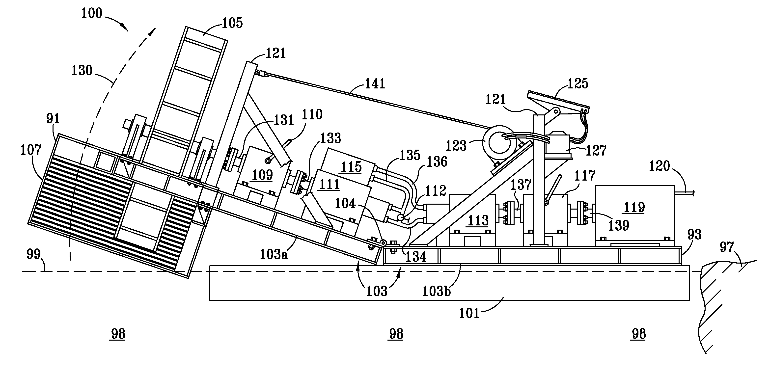
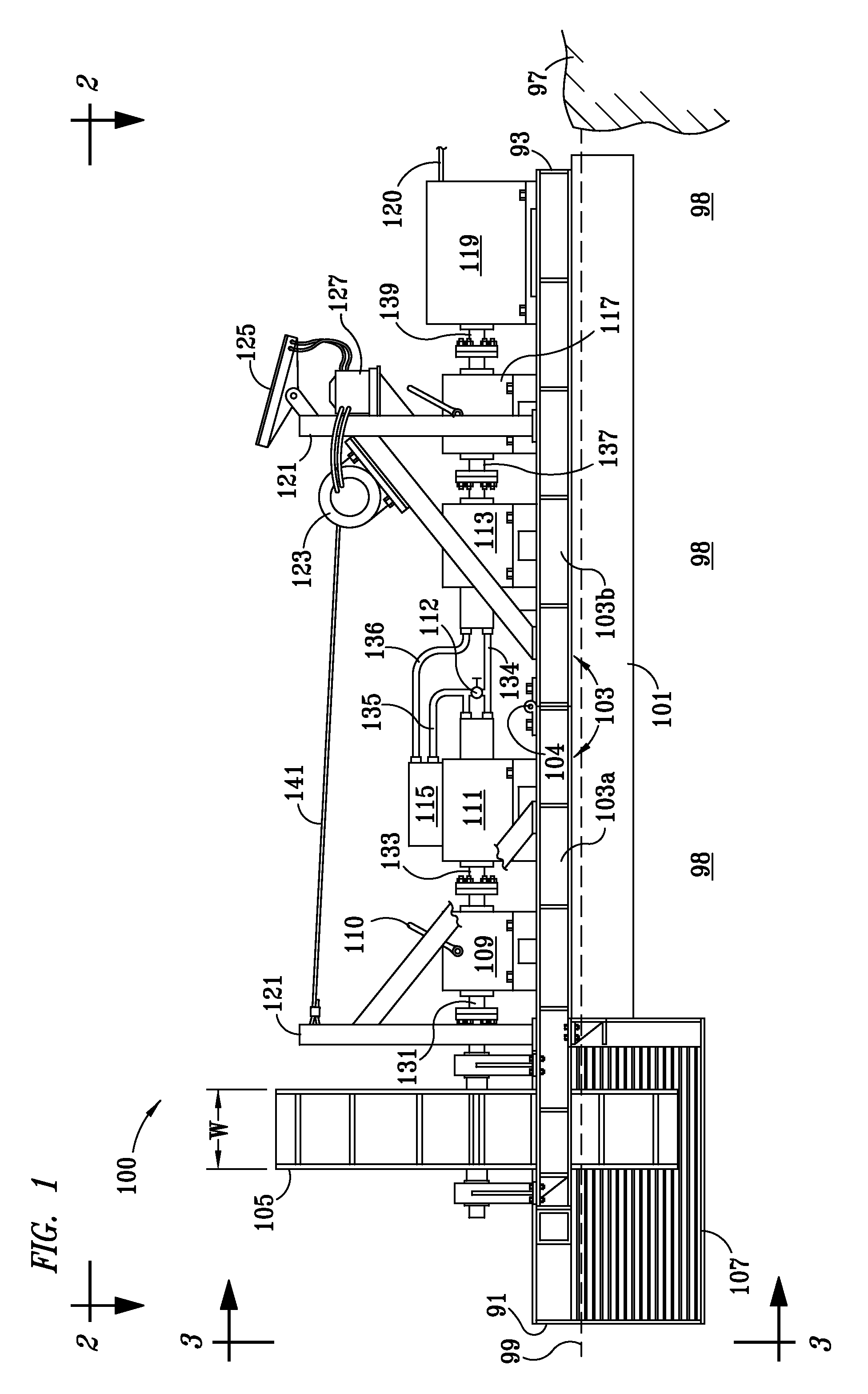
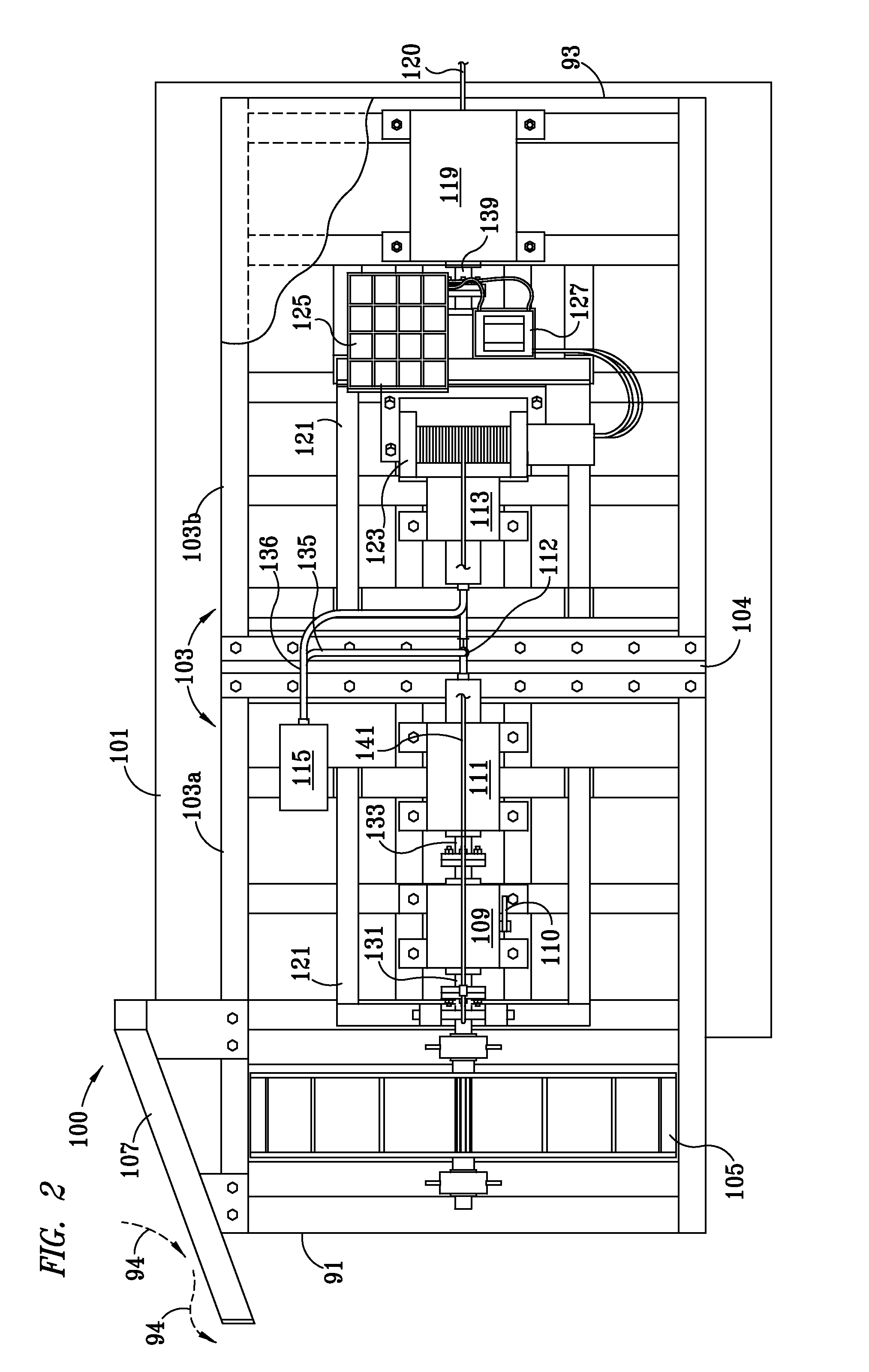
[0020]Referring to FIG. 1, there is shown a frontal elevation view of a system 100 embodying features of the present invention. The system 100 includes a river barge or floating barge 101 for providing flotation of the system 100 during operati...


PUM


Abstract

A system and method for generating electric power includes a barge with a frame mounted thereon. A paddlewheel is rotationally mounted on one end of the barge to provide rotational torque to a first transmission. The first transmission drives a hydraulic pump for pumping hydraulic fluid to a hydraulic motor. The hydraulic motor drives a second transmission which is operable to drive an electric generator for generating electricity. During operation, the force of naturally flowing water turns the paddlewheel. This in turn provides rotational power to drive the transmissions, hydraulic pump and hydraulic motor. The frame may further be divided into two hingedly connected portions. One portion of the frame may be rotated out of the water to control the turning of the paddlewheel as well as perform maintenance on the paddlewheel.

Description

TECHNICAL FIELD OF INVENTION[0001]The invention relates generally to a system and method for generating electricity and, more particularly, to a system and method for generating electricity through the use of a paddlewheel attached to a barge, wherein the force of running water is utilized to turn the paddlewheel, and correspondingly to turn an electric generator which generates electricity.BACKGROUND OF THE INVENTION[0002]In many areas, there are flowing bodies of water such as streams and rivers where a continuous, natural source of flowing water is readily and constantly available. These bodies of water typically flow towards larger bodies of water such as a lake or an ocean at a substantially low flow speed, such as in the range of 3-4 miles per hour. This speed of the water flow is generally consistent, save for the initial flow from an upstream source such as where the water source originates from melting snow or ice high up on a mountain or some other higher altitude location...

Claims


Application Information

Patent Timeline
Patent Type & Authority Patents(United States)
IPC IPC(8): F03B13/12
CPCF03B17/063F05B2240/93F05B2260/406Y02E10/28Y02E10/20
Inventor HUEBNER, ROBERT L.
Owner HUEBNER ROBERT L
Why Eureka
Try Eureka