Image sensing device, image sensing device control method, and program for the control method

a technology of image sensing and control method, which is applied in the direction of camera focusing arrangement, printers, instruments, etc., can solve the problems of user cannot arbitrarily set the distance of target objects, and the focus position is not always optimized, so as to reduce the deterioration of focusing precision and reduce the focusing resolution. , the effect of reducing the focusing resolution

Inactive Publication Date: 2013-12-17
HITACHI INFORMATION & CONTROL SOLUTIONS LTD
View PDF12 Cites 0 Cited by
  • Summary
  • Abstract
  • Description
  • Claims
  • Application Information

AI Technical Summary

Benefits of technology

[0018]Therefore, the present invention is made in consideration of the aforementioned problems, and an object of the present invention is to provide an image sensing device, an image sensing device control method, and a program for the control method which acquire the stable in-focus position for the target object, while avoiding the frequent use of the auto-focus control.

Problems solved by technology

Thus, there has been an out-of-focus problem which is caused, for example as shown in FIG. 4, when the auto-focus control is performed on the wide-side having a lower focus-driving resolution, and subsequently the manual-focus-trace control is performed on the tele-side having a greater focus-driving resolution, at the target object distance which has been set.
Furthermore, the technique disclosed in JP 2006-215285 A has the identical problem as that in the technique disclosed in JP 2005-62665 A, when the auto-focus control is enabled in the wide-side.
In addition, when the auto-focus control is disabled on the wide-side, the auto-focus control is not performed on the wide-side, thus, the focus-lens position is not always optimized, and consequently a deterioration problem of the focusing precision is caused.
In the technique disclosed in JP H11-281869 A, there has been a problem that the user cannot arbitrarily set a target object distance depending on the target object during the zoom-lens operation, since the focus-lens position, during the zoom-lens operation, is fixed to a pre-determined target object distance such as the infinity or the like for the control purpose.

Method used


Image

  • Image sensing device, image sensing device control method, and program for the control method
  • Image sensing device, image sensing device control method, and program for the control method
  • Image sensing device, image sensing device control method, and program for the control method

Examples


modified example

[0100]As above, one embodiment of the present invention is described. However, it should be further understood by those skilled in the art that the present invention is not limited to the embodiment set forth hereinabove and may take on modifications and alterations without departing from the spirit of the present invention, for example, as follows.

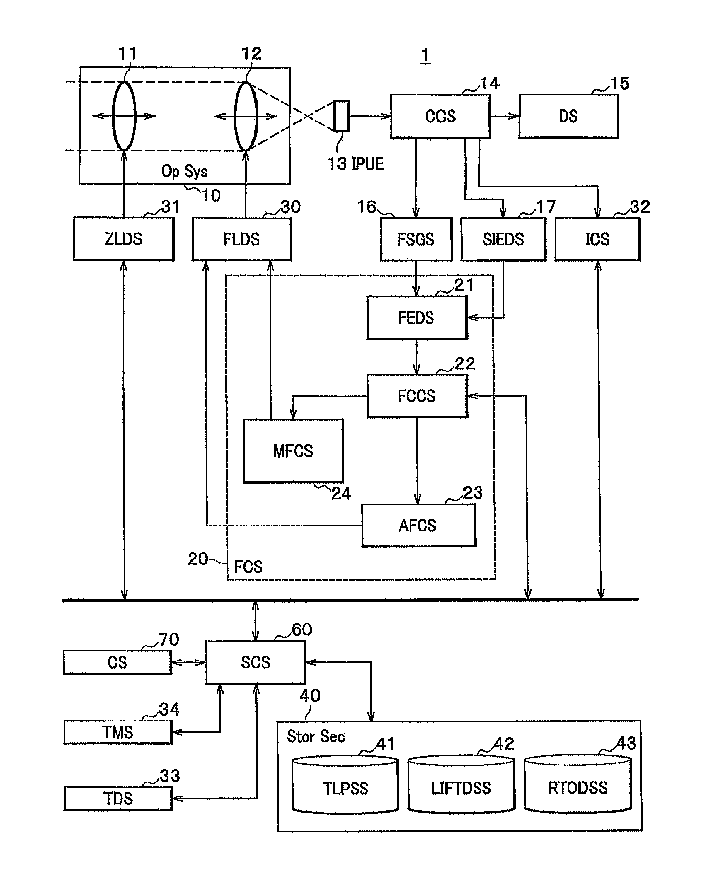
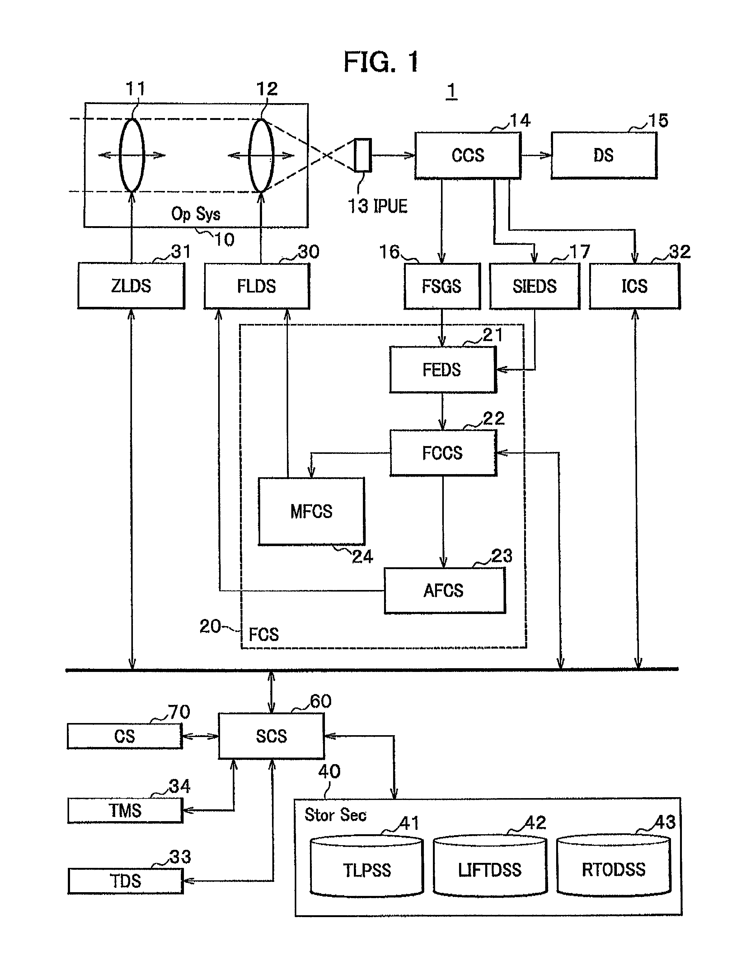
[0101]The present invention is, in light of the driving life of the focus-lens 12 (focus adjustment lens), especially effective for the surveillance cameras which perform a long-time video-shooting and in addition, also effective for other image sensing devices such as professional cameras, video cameras, digital video cameras and the like.

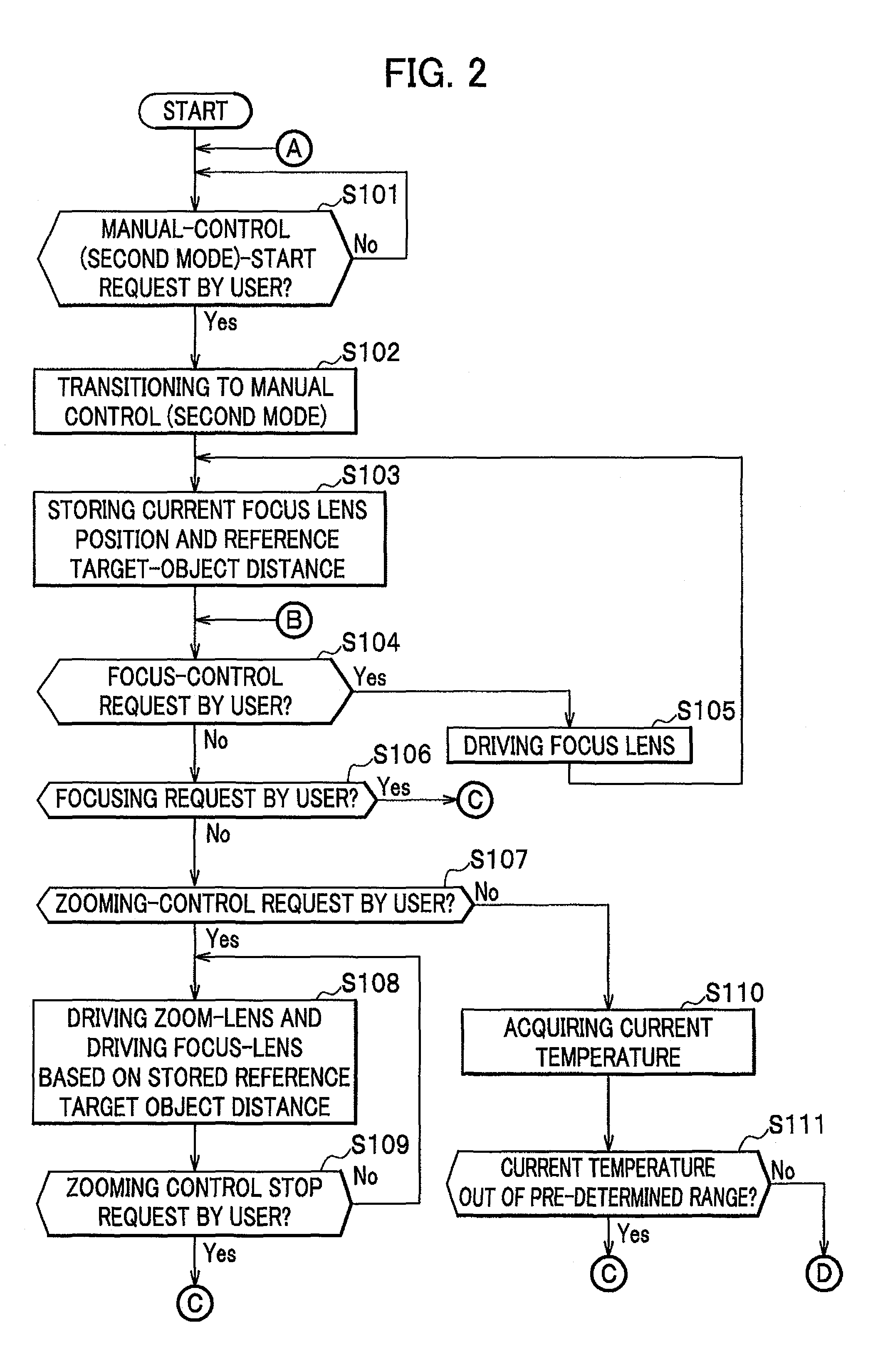
[0102]Moreover, in the step S110, the image sensing device 1 acquires the current temperature. However the image sensing device 1 may acquire the current temperature immediately after the steps S103 and S113 and may determine whether the temperature difference between both of the above temperatures is o...


PUM


Abstract

For preventing frequent use of auto-focus control and also for acquiring stable in-focus positions for target-objects, this invention comprises system control section 60 having a second mode to drive magnification adjustment lens 11 or focus adjustment lens 12 upon a user command, and a third mode to transition to a first mode under pre-determined conditions in the second mode, and to set in-focus states of a lens group, wherein system control section 60 stores a reference target-object distance in reference target-object distance storage section 43 when focus adjustment lens 12 is driven by user commands in the second mode, drives focus adjustment lens 12 not based on a current target-object distance but the lens in-focus trajectory data to retain the reference target-object distance when the magnification adjustment lens 11 is driven by user commands, and re-transitions to the second mode without updating the reference target-object distance, after the third mode.

Description

CROSS REFERENCE TO RELATED APPLICATION[0001]This application claims priority under 35 U.S.C. §119 to Japanese Patent Application No. 2010-281444 filed on Dec. 17, 2010, the disclosure of which is incorporated herein by reference.BACKGROUND OF THE INVENTION[0002]1. Field of the Invention[0003]The present invention relates to an image sensing device, more particularly, to an image sensing device which is capable of switching an auto-focus control and a manual control.[0004]2. Description of the Related Art[0005]In image sensing devices such as surveillance cameras, video cameras, or the like, the auto-focus control and the manual control are extensively utilized. Further, the manual control includes two types which are a manual-focus control and a manual-focus-trace control. Incidentally, in this specification, the auto-focus control is denoted by a first mode, and the manual control is denoted by a second mode.[0006]The auto-focus control is a control for performing focus adjustment ...

Claims


Application Information

Patent Timeline
Patent Type & Authority Patents(United States)
IPC IPC(8): G03B13/36
CPCG02B7/28G03B13/36H04N5/23212H04N23/675
Inventor ANDO, AKIRAYOKOYAMA, TOSHIYUKINISHIGUCHI, TOMOAKI
Owner HITACHI INFORMATION & CONTROL SOLUTIONS LTD
Why Eureka
Try Eureka