Internet connection switch and internet connection system

a switch and internet connection technology, applied in the field of internet connection switch and internet connection system, can solve the problems of system configuration complicated, devices connected to different route complexes cannot hold communication between devices, and devices (such as cpus) connected to different route complexes cannot broadcast data to the same endpoint in the system, so as to prevent an increase in the delay of data transfer and the effect of large lsi circuit scal

Active Publication Date: 2013-12-24
NEC CORP
View PDF18 Cites 4 Cited by
  • Summary
  • Abstract
  • Description
  • Claims
  • Application Information

AI Technical Summary

Benefits of technology

[0028]The third problem is that the PCI express switch shown in FIG. 26 does not include a multicast transfer function with respect to specific devices. Due to this, two types of switches, that is, the network switch 401 and the PCI express switch 104 are necessary. This disadvantageously makes a system configuration complicated, increases cost and makes system operation complex.
[0033]According to the present invention, in the system using the PCI express, communication can be held between such devices as CPUs without a frame encapsulation processing. This can thereby prevent an increase in delay during data transfer and an LSI circuit scale from being made large.

Problems solved by technology

The first problem is that devices (such as the CPU) connected to the route complex cannot hold communication between the devices in the system using the PCI express shown in FIG. 25.
The second problem is that devices (such as CPUs) connected to different route complexes cannot broadcast data to the same endpoint in the system using the PCI express shown in FIG. 25.
The third problem is that the PCI express switch shown in FIG. 26 does not include a multicast transfer function with respect to specific devices.
This disadvantageously makes a system configuration complicated, increases cost and makes system operation complex.

Method used


Image

  • Internet connection switch and internet connection system
  • Internet connection switch and internet connection system
  • Internet connection switch and internet connection system

Examples


Embodiment Construction

[0068]Modes for carrying out the present invention will be described hereinafter in detail with reference to the drawings.

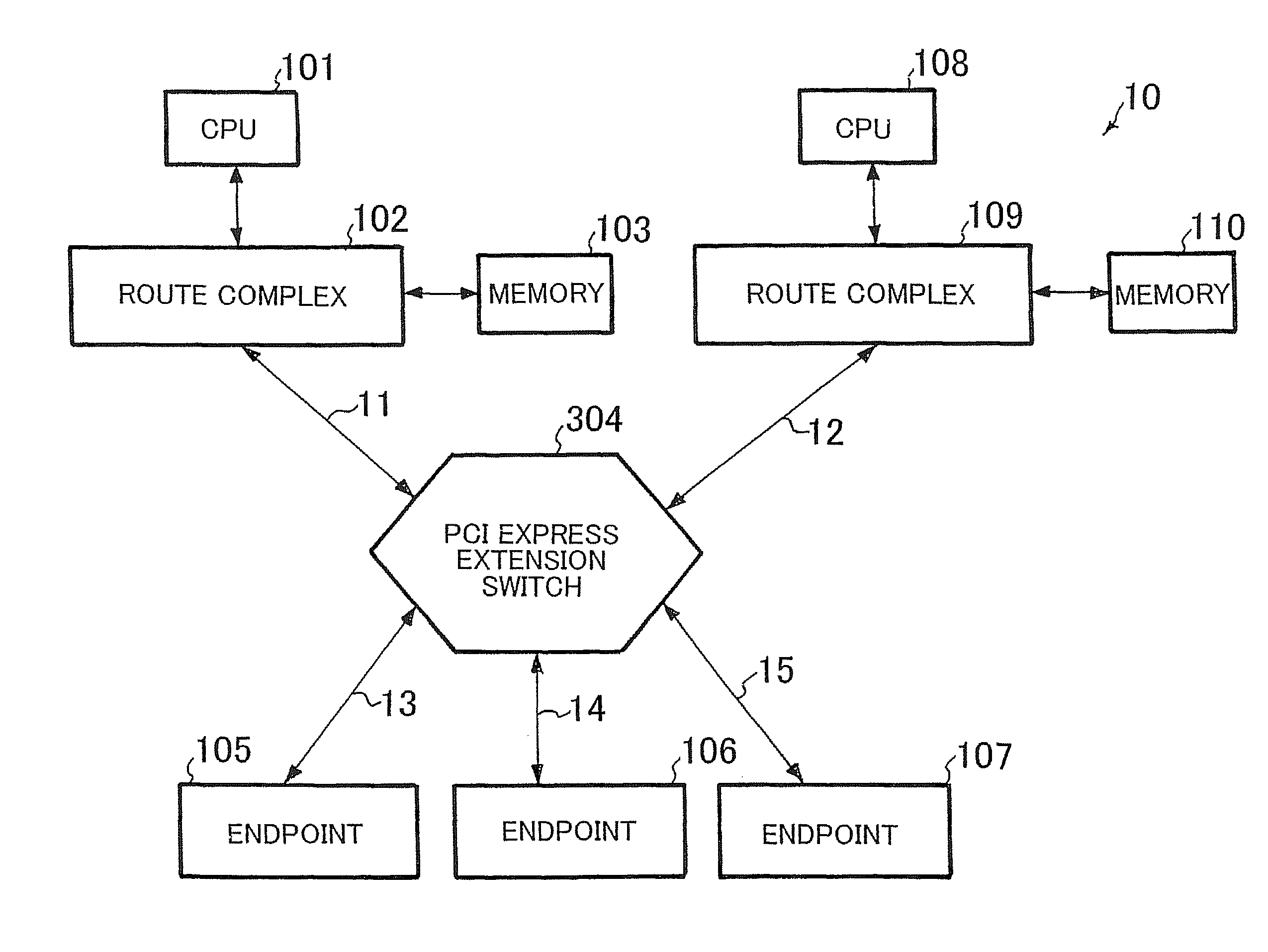
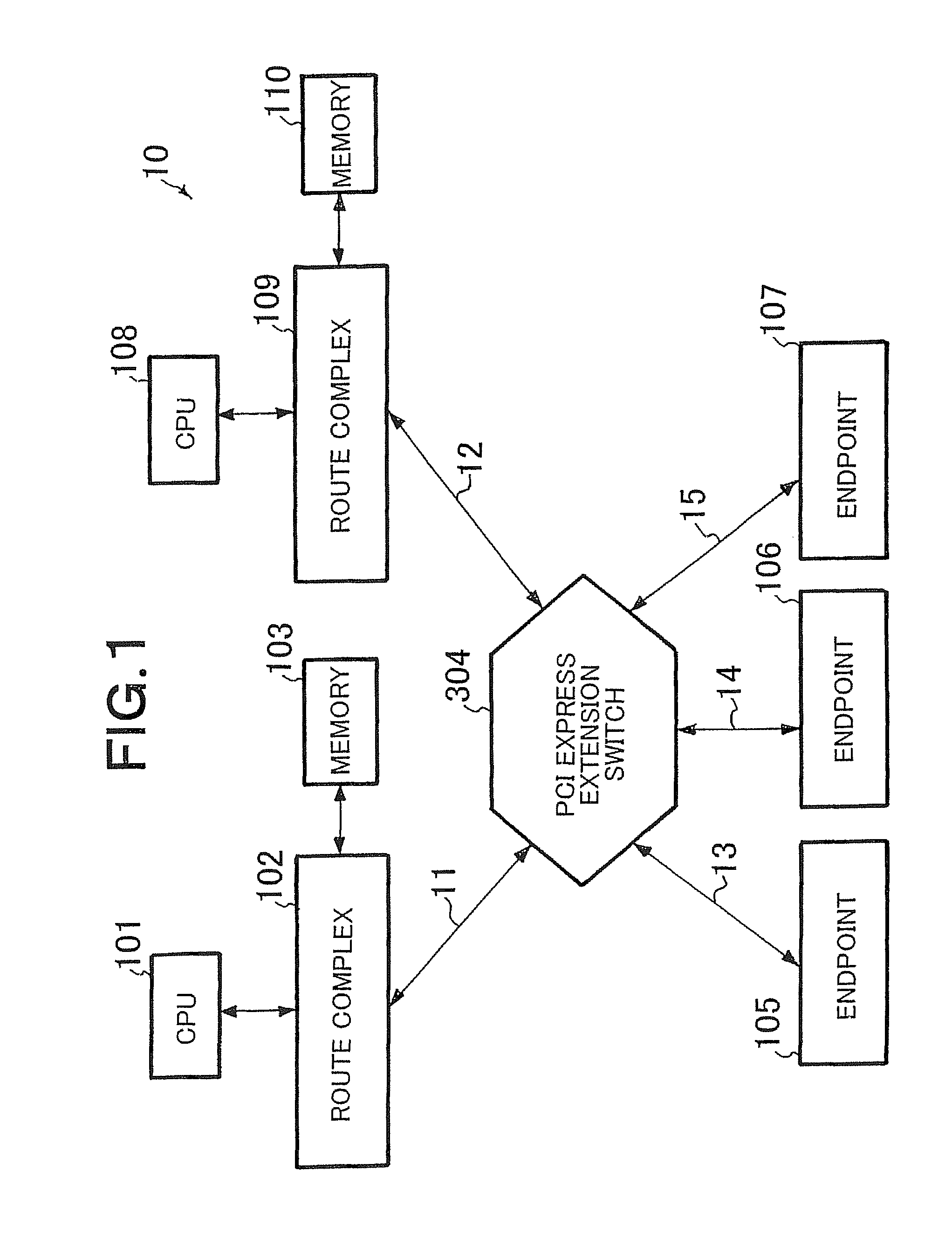
[0069]FIG. 1 shows a configuration of a system according to an embodiment of the present invention. A PCI express system 10 is configured so that a plurality of route complexes 102 and 109 and a plurality of endpoints 105 to 107 are connected to a PCI express extension switch 304 corresponding to a switch according to the present invention via PCI express buses 11 to 15, respectively. A CPU 101 and a memory 103 are connected to the route complex 102 whereas a CPU 108 and a memory 110 are connected to the route complex 109.

[0070]Each of the route complexes 102 and 109 and the endpoints 105 to 107 is a device complying with the PCI express and including a function of holding data communication using an address routing TLP frame shown in FIG. 21 and an ID routing TLP frame shown in FIG. 22.

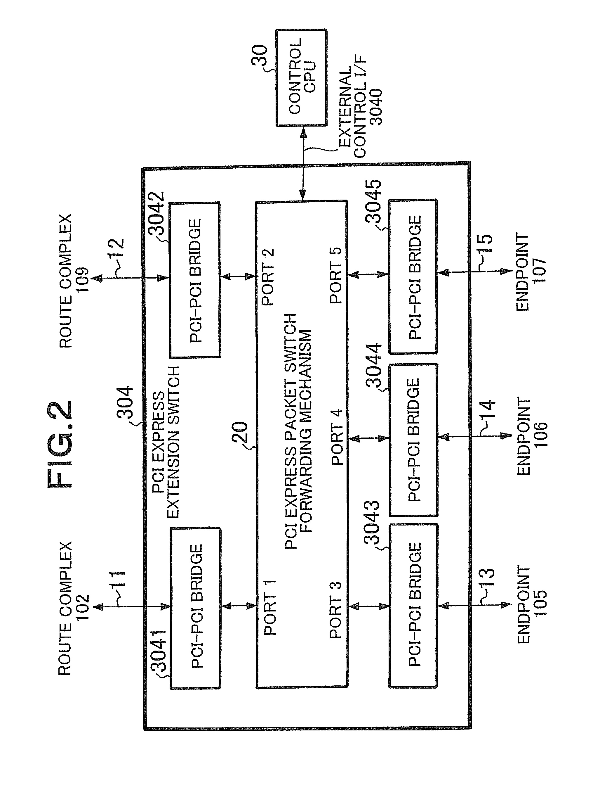
[0071]FIG. 2 shows a configuration of the PCI express extension switch 304. T...


PUM


Abstract

A switch (304) includes a plurality of bridges (3041, 3042, 3043, 3044, 3045) and a switch forwarding mechanism (20). Each of the bridges transmits and receives a TLP frame complying with PCI express to and from a device connected to each of the bridges. The switch forwarding mechanism includes a plurality of ports (1, 2, 3, 4, 5) to which the bridges are connected, respectively, selects an output port in dependence on a combination of destination information on the TLP frame input from one of the plurality of ports and the port which input the TLP frame, and outputs the TLP frame from the selected output port.

Description

[0001]This application is the National Phase of PCT / JP2007 / 065488, filed Aug. 8, 2007, which is based upon and claims the benefit of priority from Japanese patent application No. 2006-216495, filed on Aug. 9, 2006, the disclosure of which is incorporated herein in its entirety by reference.TECHNICAL FIELD[0002]The present invention relates to a switch for interconnection for extending a PCI express interface of a computing device and a networking device used in a computer and a network apparatus and a system using the switch.BACKGROUND ART[0003]A peripheral component interconnect (PCI) has achieved its popularity as a bus standard for establishing connection among computing devices such as a central processing unit (CPU), a hard disk and a graphic controller, among networking devices such as a forwarding engine and a network controller or among computing devices and networking devices. As a next generation standard to this PCI, a PCI express using a serial bus in place of a parallel...

Claims


Application Information

Patent Timeline
Patent Type & Authority Patents(United States)
IPC IPC(8): G06F13/00
CPCG06F13/4022
Inventor HIDAKA, YOUICHISUZUKI, JUNHIGUCHI, JUNICHIYOSHIKAWA, TAKASHI
Owner NEC CORP
Why Eureka
Try Eureka