Contact terminal

a terminal and contact technology, applied in the field of contact terminals, can solve the problems of user injury, damage to the external environment, and inconvenience of users, and achieve the effects of improving the appearance of a product, ensuring the durability of the product, and stable connection structur

Active Publication Date: 2014-03-11
SAMSUNG ELECTRONICS CO LTD
View PDF35 Cites 18 Cited by
  • Summary
  • Abstract
  • Description
  • Claims
  • Application Information

AI Technical Summary

Benefits of technology

[0013]Accordingly, the present invention has been made to solve the above-mentioned problems occurring in the prior art and provides additional advantages, by providing a contact terminal which is inexpensive and provides a better aesthetic appearance and durability.
[0014]Another aspect of the present invention provides a contact terminal whose exposure to the exterior is minimum, thus improving an outer appearance of a portable terminal or a docking cradle.
[0018]According to the above-mentioned contact terminal, the contact pin can be connected to a counterpart while being supported by the plate spring, thereby ensuring a stable connection structure. Then, only one end of the contact pin is exposed to the outside of a portable terminal or a docking cradle, thus improving an appearance of a product. In addition, since a load applied to the plate spring can be adjusted by adjusting a length of the contact pin, in particular, a length of a portion of the contact pin exposed to the outside of the product, the durability of the product can be easily guaranteed without supporting the plate spring with a separate resilient body. Further, the product can be manufactured at a lower cost which in turn contributes to a reduction of manufacturing costs.

Problems solved by technology

Also, as a predetermined area of the C-clip is exposed to external to provide a stable connection, an outer aesthetic appearance of the portable terminal is suffered.
Further, since the C-clip is manufactured by bending a plate, a sharp portion may be formed at a side thereof, in which case a user may be injured or an external environment may be damaged.
Although the pogo pin has a higher quality and provide a better outer appearance than that of a plate spring, the pogo pin cost more, thereby increasing the manufacturing costs of the portable terminal.
Further, noise is generated by relative movement between components of the pogo pin itself which is a drawback and undesirable during operation.

Method used


Image

  • Contact terminal
  • Contact terminal
  • Contact terminal

Examples


Embodiment Construction

[0026]Hereinafter, exemplary embodiments of the present invention will be described with reference to the accompanying drawings. For the purposes of clarity and simplicity, a detailed description of known functions and configurations incorporated herein will be omitted as it may make the subject matter of the present invention unclear.

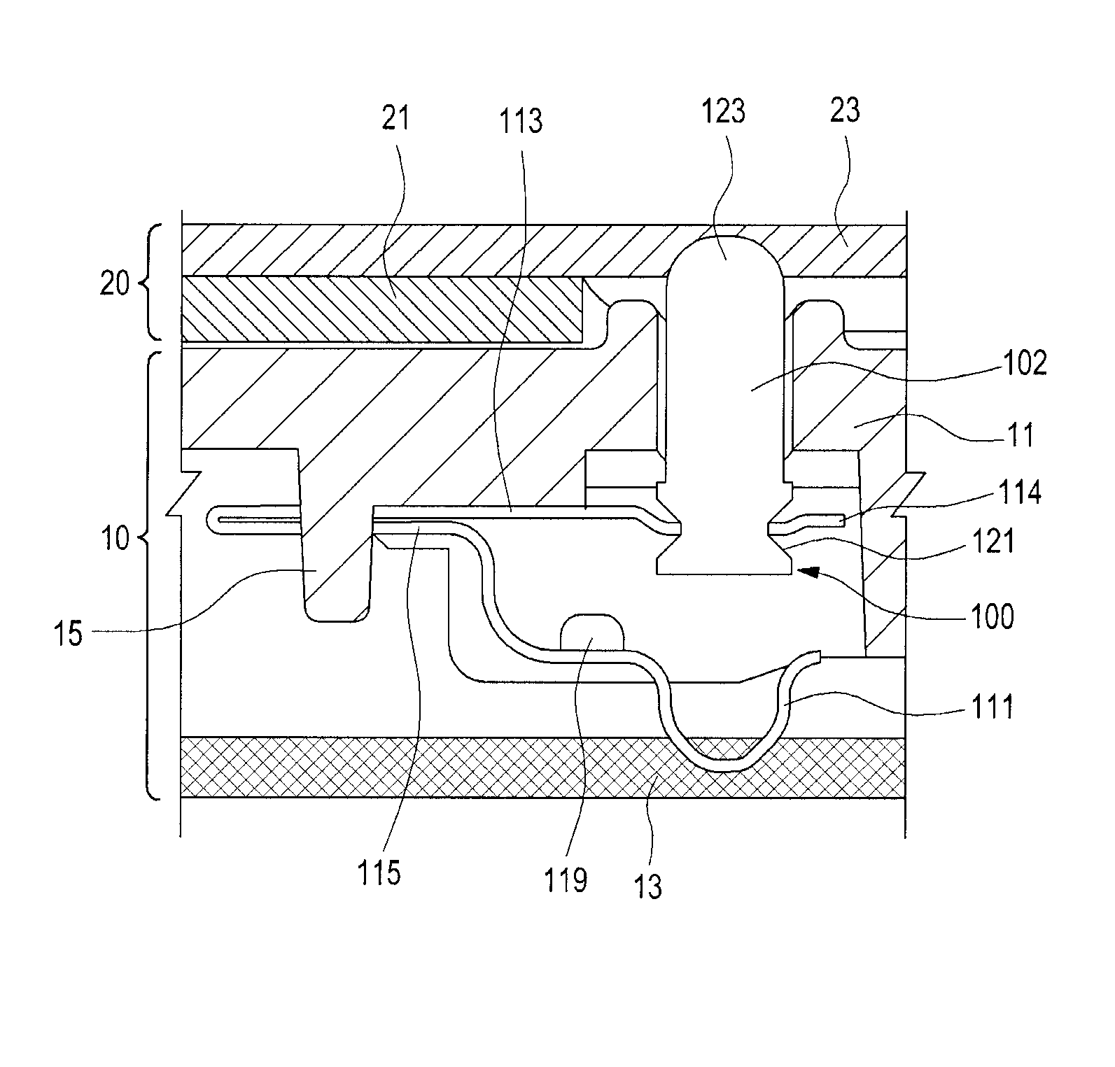
[0027]Referring to FIGS. 5 and 6, a contact terminal 100 according to an embodiment of the present invention includes a plate spring 101 and a contact pin 102. The plate spring 101 is mounted within a body housing 11 of a product 10 such as a portable terminal or a docking cradle, and a portion of the contact pin 102 protrudes to the outside of the body housing 11 while the contact pin 102 is being supported by the plate spring 101. A counterpart 20 of, for example, a battery pack or a battery cover, is coupled to the body housing 11, and a connection piece 23 is installed within a housing 21 (hereinafter, referred to as ‘a second housing’) of the coun...


PUM


Abstract

A contact terminal includes: a contact pin; and a plate spring configured to support the contact pin, wherein a portion of the plate spring is connected to a circuit board, wherein the contact pin can be connected to a counterpart while being supported by the plate spring, thus ensuring a stable connection structure.

Description

CLAIM OF PRIORITY[0001]This application claims the priority under 35 U.S.C. §119(a) of an application entitled “Contact Terminal” filed in the Korean Intellectual Property Office on Aug. 3, 2011 and assigned Serial No. 10-2011-0077321, the contents of which are hereby incorporated by reference.BACKGROUND OF THE INVENTION[0002]1. Field of the Invention[0003]The present invention relates to an electronic component, and more particularly to a contact terminal which provides a connection between two different parts such as a battery pack of a portable electronic device and various cables.[0004]2. Description of the Related Art[0005]In general, portable terminals house detachable battery packs and devices which require electrical connections between two different components such as a communication cable and a memory card socket. A docking cradle for a portable terminal further include various types of contact terminals.[0006]For example, a portable terminal having a detachable battery pa...

Claims


Application Information

Patent Timeline
Patent Type & Authority Patents(United States)
IPC IPC(8): H01R13/24
CPCH01R13/2442H01R13/2435H01R12/714H01R13/08H01R4/48H01R13/24
Inventor PARK, JE-MINHWANG, SUNG-JUN
Owner SAMSUNG ELECTRONICS CO LTD
Why Eureka
Try Eureka