Check patentability & draft patents in minutes with Patsnap Eureka AI!

Simplified cooling circuit for powertrain braking system

a cooling circuit and powertrain technology, applied in the field of powertrains, can solve the problems of complex hardware and control logic, and achieve the effect of reducing parasitic losses

Active Publication Date: 2014-11-18
DEERE & CO
View PDF3 Cites 2 Cited by
  • Summary
  • Abstract
  • Description
  • Claims
  • Application Information

AI Technical Summary

Benefits of technology

[0008]In one form, the invention includes a powertrain assembly with an integral brake assembly, the powertrain assembly including a housing and a torque-carrying power shaft. A brake assembly includes interdigitated annular friction plates respectively connected to the housing and to the torque-carrying power shaft. A liquid lubricant and cooling circuit provides liquid between the annular friction plates for distributing liquid between the annular friction plates when the plates are engaged with one another and around and through the annular friction plates when the plates are disengaged as a function of the displacement of said friction plates relative to one another and to said housing for reducing parasitic losses when the brake assembly is not engaged.

Problems solved by technology

While this is one attempt to minimize the expenditure of energy, it requires a complicated set of hardware and of control logic to achieve the end.

Method used


Image

  • Simplified cooling circuit for powertrain braking system
  • Simplified cooling circuit for powertrain braking system
  • Simplified cooling circuit for powertrain braking system

Examples


Embodiment Construction

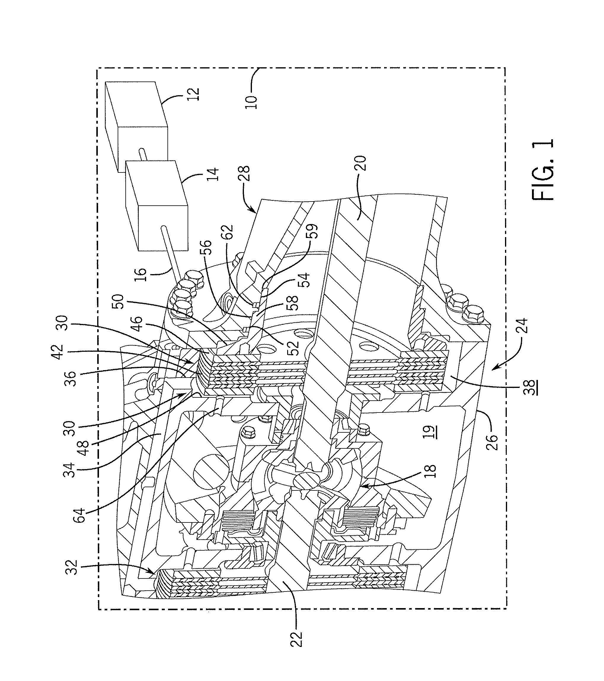
[0015]Referring now to the drawings, and more particularly to FIG. 1, there is shown a work machine 10 having a prime mover 12 which may be a diesel engine mechanically interconnected to a transmission 14 and an input shaft 16 extending to a differential 18 powering right and left shafts 20 and 22 respectively. Shafts 20 and 22 are torque-carrying and are contained within a housing 24 and extend to driving wheels (not shown) for work machine 10. Shafts 20 and 22 may also power epicyclic gear reduction assemblies (also not shown) adjacent the wheels to provide vehicle velocity control.

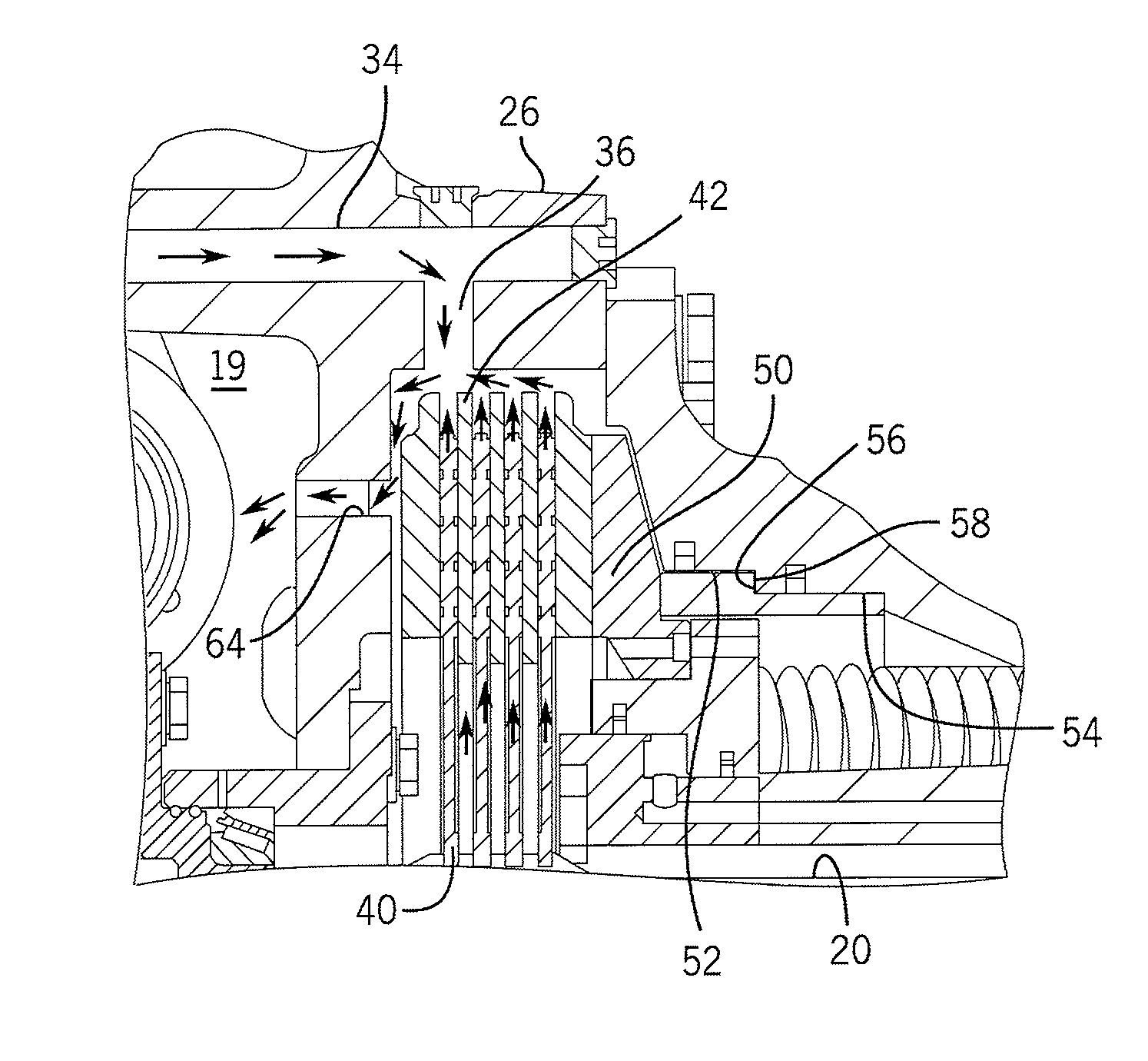
[0016]The housing 24 contains a central housing 26, generally annular in form, which provides a support and journaling for all of the interior elements and right and left extensions 28 for journaling and housing axles 20 and 22. The central housing 26 encompasses a chamber 19 for the differential 18 and provides a sump for lubrication and cooling fluid to be described later.

[0017]Each of the axles 20 an...


PUM


Abstract

An efficient lubrication system for wet plate brake assemblies includes a flow control system that passes lubricant for cooling and lubrication through interdigitated wet brake plates when the plates are engaged. When the plates are disengaged, the wet plate assembly is controlled to limit its displacement by means of a pin and spring such that a gap is provided around the brake plates to provide a preferential path for lubricant, thus minimizing parasitic losses.

Description

BACKGROUND OF THE INVENTION[0001]1. Field of the Invention[0002]The present invention relates to powertrains of work machines, and, more specifically, to integrated braking systems for such machines.[0003]2. Description of the Related Art[0004]For many years, work machines have incorporated brake assemblies within their powertrain and, more specifically, adjacent the torque-carrying shafts spaced from the wheels for such vehicles. Typically, these brake assemblies comprise a series of interdigitated annular plates that are respectively connected to a housing in which they are positioned and to a torque-carrying power shaft. The brake assemblies are activated by an external piston that forces the brake disc plates together to provide a retarding force between the housing and the torque-carrying shaft. Because the friction plates are positioned within the housing, a system for lubricating the plates and for dissipating excess heat must be employed. Typically, such cooling system inclu...

Claims


Application Information

Patent Timeline
Patent Type & Authority Patents(United States)
IPC IPC(8): F16D121/02F16D65/833F16D69/00F16D65/853
CPCF16D65/853F16D2069/004F16D2121/02
Inventor CLIFF, MICHAEL J.WOOD, JR., ROBERT L.EASTMAN, BRITON T.GANAPATHI, POONGUNDRAN
Owner DEERE & CO
Features
  • R&D
  • Intellectual Property
  • Life Sciences
  • Materials
  • Tech Scout
  • Unparalleled Data Quality
  • Higher Quality Content
  • 60% Fewer Hallucinations
Learn More