Actuation system for leading edge high-lift device

a technology of actuation system and high-lift device, which is applied in the direction of wing lift eficiency, aircraft stabilisation, wing adjustment, etc., can solve the problems of heavy weight, difficult to optimise the position of the device in its various positions, and simple rotation is possible, so as to achieve more complex motion of the device

Inactive Publication Date: 2015-03-03
AIRBUS OPERATIONS LTD
View PDF23 Cites 7 Cited by
  • Summary
  • Abstract
  • Description
  • Claims
  • Application Information

AI Technical Summary

Benefits of technology

[0013]The present invention provides an actuation system which can impart a more complex motion to the device without incurring the disadvantages of a track mechanism. The high-lift device moves around the leading edge from the stowage position to the intermediate position with a downward drooping motion. The second actuation mechanism can then move the high-lift device from the intermediate position to a fully extended position, typically opening up a slot between the high-lift mechanism and the leading edge as it does so. The second actuation mechanism can also be operated to generate a sealing force between the high-lift device and the leading edge of the aircraft wing either in the stowage position, in the intermediate position, or in both positions.

Problems solved by technology

Associated with the performance constraints are structure and system requirements that are driving the design toward simpler, lighter and more compact devices.
A problem with these conventional arrangements is that only a simple rotation is possible.
Therefore it is difficult to optimise position of the device in its various positions.
However such track mechanisms are complex, heavy, and take up a large amount of space.

Method used


Image

  • Actuation system for leading edge high-lift device
  • Actuation system for leading edge high-lift device
  • Actuation system for leading edge high-lift device

Examples


Embodiment Construction

)

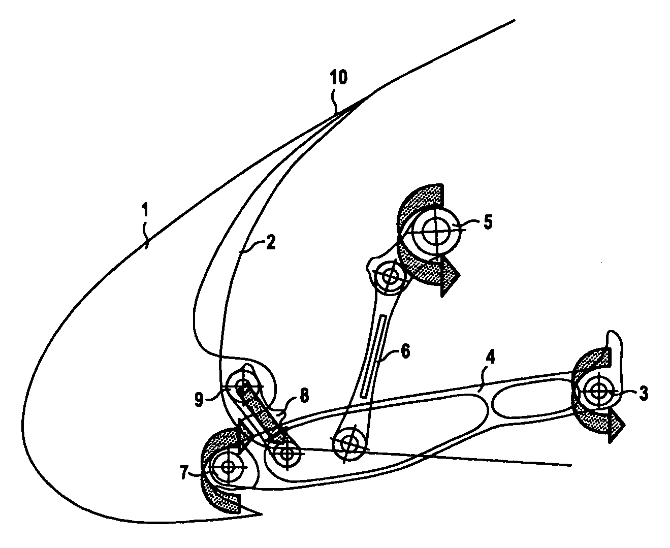
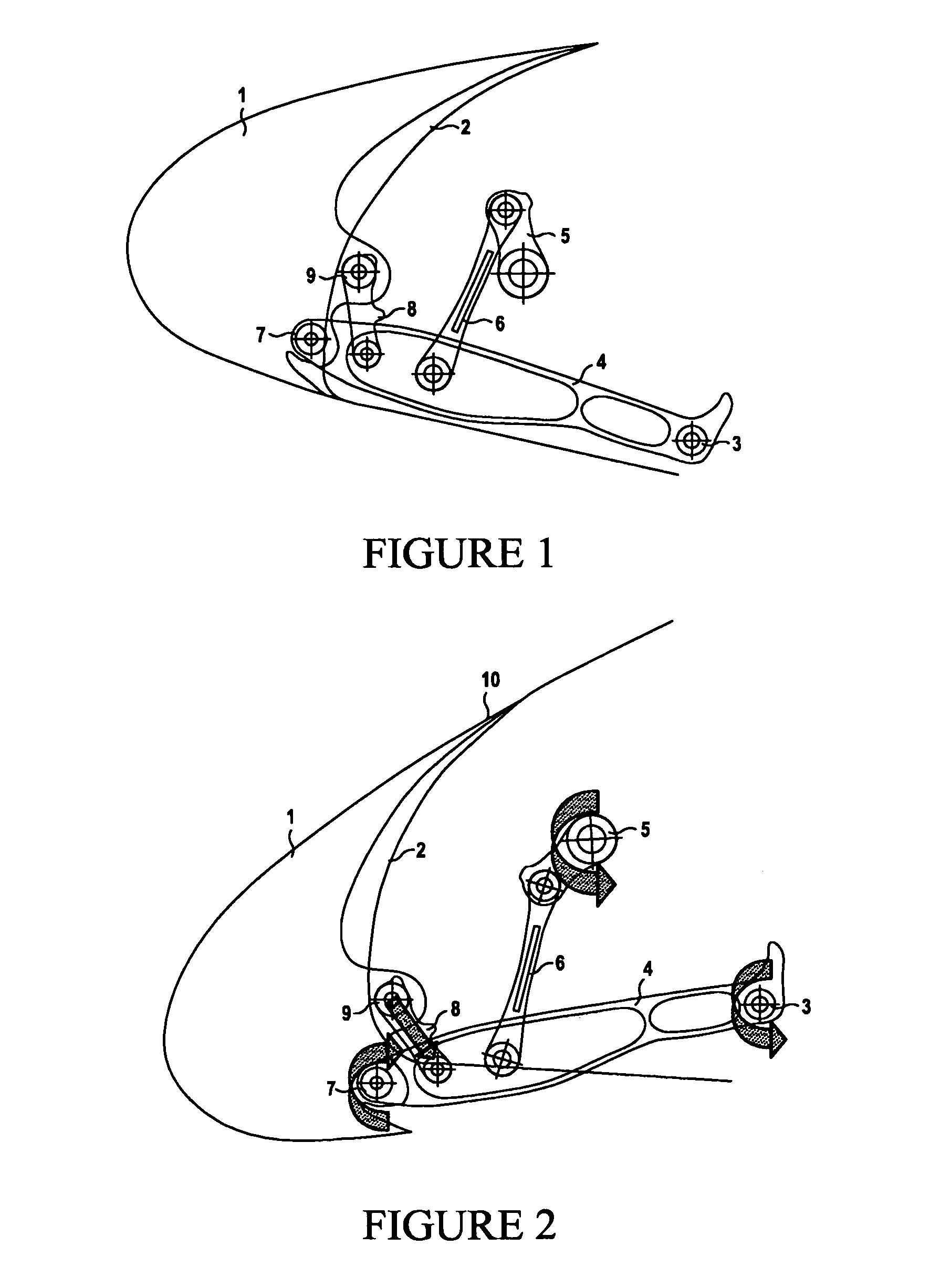
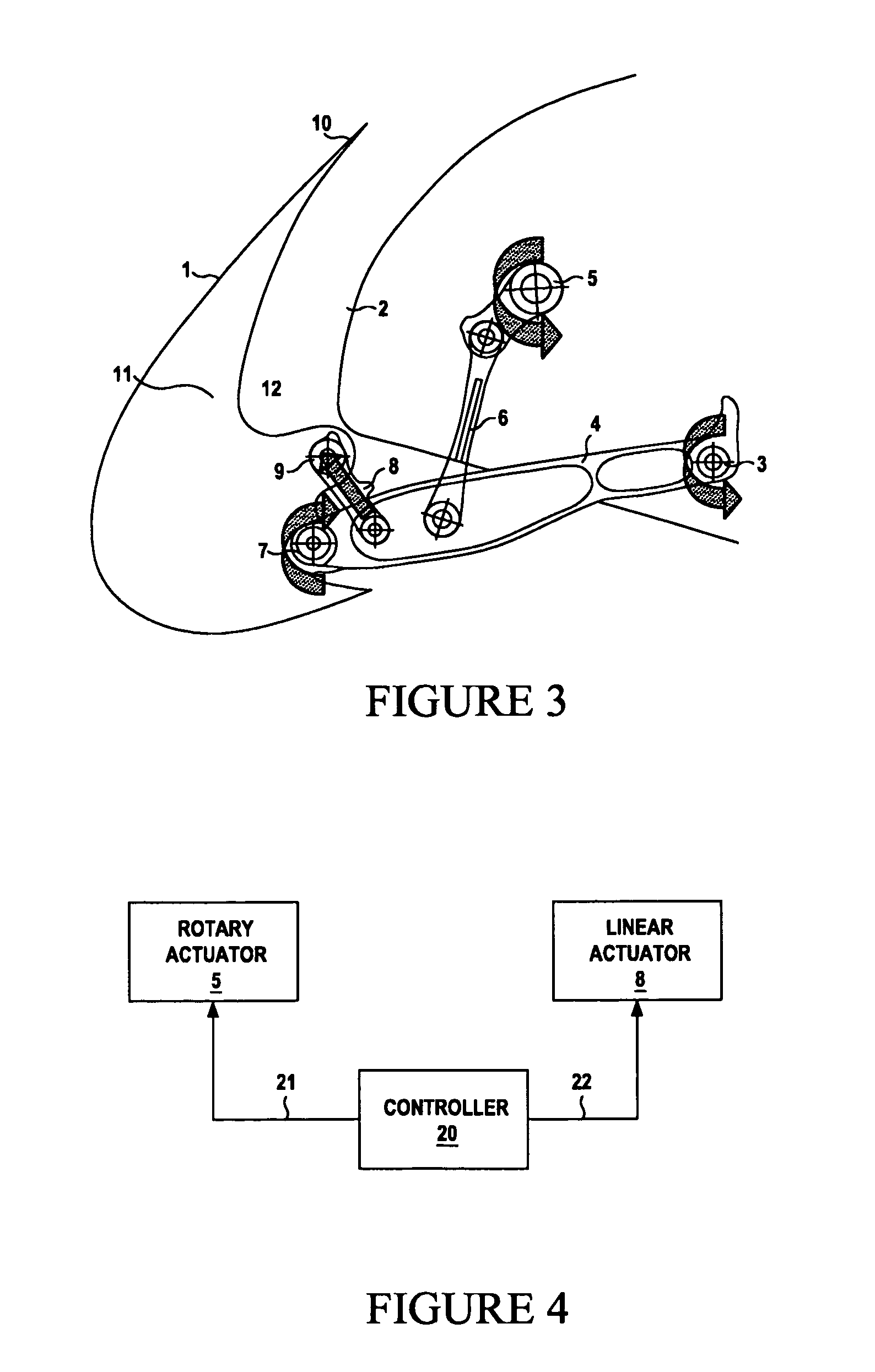
[0025]FIGS. 1-3 show a leading edge flap 1. The flap 1 is designed to improve the aircraft lift to drag ratio in the take-off phase and increase the maximum angle of attack of the aircraft thus delaying wing stall in the landing phase. FIG. 1 shows the leading edge flap in a fully retracted stowage position; FIG. 2 shows the flap in an intermediate position for maximum lift to drag ratio in take-off; and FIG. 3 shows the flap in a fully extended position for maximum aircraft angle of attack in landing.

[0026]As shown in FIG. 1, the leading edge flap 1 is mounted on a fixed leading edge 2 of the wing. The leading edge flap actuation system comprises a link 4 pivotally connected to the wing at a first pivot point 3 and to the flap at a second pivot point 7. The link 4 can be rotated about the first pivot point 3 by a first actuation mechanism comprising a rotary actuator 5 and a pair of hinged drive arms 6. The flap 1 can also be rotated about the second pivot point 7 by a second actu...


PUM


Abstract

An actuation system configured to deploy a high-lift device on a leading edge of an aircraft wing. The system comprises: a link pivotally connected to the wing at a first pivot point and to the high-lift device at a second pivot point; a first actuation mechanism configured to rotate the high-lift device about the first pivot point; and a second actuation mechanism configured to rotate the high-lift device about the second pivot point. The second actuation mechanism is operable independently of the first actuation mechanism, and can be operated in order to generate a sealing force between the high-lift device and the leading edge of the aircraft wing.

Description

[0001]This application is the U.S. national phase of International Application No. PCT / GB2008 / 050996 filed 27 Oct. 2008, which designated the U.S. and claims priority to GB Application No. 0721284.8 filed 31 Oct. 2007, the entire contents of each of which are hereby incorporated by reference.FIELD OF THE INVENTION[0002]The present invention relates to a method and actuation system for deploying a high-lift device on a leading edge of an aircraft wing.BACKGROUND OF THE INVENTION[0003]Modern aircraft require greater performance from their high lift devices while trying to minimise their structure and system impact. High lift systems need to provide a high lift to drag ratio during take-off, while achieving maximum lift and therefore maximum angle of attack at landing.[0004]Associated with the performance constraints are structure and system requirements that are driving the design toward simpler, lighter and more compact devices.[0005]Interference between high lift leading edge device...

Claims


Application Information

Patent Timeline
Patent Type & Authority Patents(United States)
IPC IPC(8): B64C3/50B64C9/14B64C9/24
CPCB64C9/24B64C2009/143Y02T50/32Y02T50/30
Inventor CATHELAIN, FRANCOISKAY, EDMUND
Owner AIRBUS OPERATIONS LTD
Why Eureka
Try Eureka