Multi-stage planetary vehicle transmission

a multi-stage, planetary technology, applied in the direction of gearing details, gearing, transportation and packaging, etc., can solve the problems of drag loss, and achieve the effect of little structural complexity and improved efficiency

Inactive Publication Date: 2015-03-31
ZF FRIEDRICHSHAFEN AG
View PDF13 Cites 44 Cited by
  • Summary
  • Abstract
  • Description
  • Claims
  • Application Information

AI Technical Summary

Benefits of technology

[0005]Consequently, the purpose of the present invention is to propose a multi-gear transmission of the type described to begin with, which has better efficiency and little structural complexity and whose shifting elements are arranged optimally as regards their actuation.
[0008]In that the first shaft is the drive input or drive input shaft and is or can be connected respectively to the sun gear of the first and third planetary gearsets and respectively to the planetary carriers of the first and second planetary gearsets and also to the housing, the second shaft is the drive output or drive output shaft and is or can be connected to the ring gear of the fourth planetary gearset and to the planetary carrier of the third planetary gearset, the ring gear of the first planetary gearset is or can be connected to the sun gear of the second planetary gearset and to the planetary carrier of the fourth planetary gearset, the ring gear supports of the second and third planetary gearsets are or can be connected, and the sun gear of the fourth planetary gearset can be connected to the housing, a multi-gear transmission according to the invention is obtained which preferably enables actuation of the shifting elements in an efficiency-improving manner because the shifting elements are easily accessible from the outside. Moreover, due to the connections chosen according to the invention between the elements of the transmission, an optimized series of transmission ratios and low absolute and relative rotation speeds as well as low planetary gearset and shifting element torques are obtained in the multi-gear transmission proposed. Furthermore, thanks to the arrangement of the gearsets gearing efficiencies are improved and components loads are low while there is little structural complexity, so the production costs and the weight of the multi-gear transmission are advantageously reduced.
[0011]The good accessibility of the shifting elements is achieved, among other things, on the one hand by using brakes as shifting elements and on the other hand with clutches as shifting elements, which are positioned on external shafts, preferably on the drive input and the drive output in the multi-gear transmission according to the invention.
[0015]The term shifting element is understood to mean a shiftable connection between two elements of the transmission such that the torque to be transmitted between the two elements is transferred by force or friction locking or by shape interlock. If both elements of the shiftable connection are designed to rotate the shifting element is called a clutch, whereas if only one of the two elements of the shiftable connection rotates, the shifting element is called a brake. Moreover, the geometrical position or sequence of the individual shifting elements can also be chosen freely provided that it allows appropriate connections between the elements. In this way the position of individual elements can be displaced as desired. Example embodiments of frictional shifting elements are disk clutches or disk brakes, band brakes, conical clutches or brakes, electromagnetic clutches, magnetic particle clutches or electro-rheological clutches. Example embodiments of interlocking shifting elements are claw clutches or brakes and tooth clutches.
[0016]Preferably, by virtue of their nature above all the first shifting element and the fifth shifting element can be in the form of interlocking shifting elements, which brings clear fuel consumption advantages.

Problems solved by technology

Thus, owing to the open disk shifting elements undesired drag losses occur.

Method used


Image

  • Multi-stage planetary vehicle transmission
  • Multi-stage planetary vehicle transmission
  • Multi-stage planetary vehicle transmission

Examples


first embodiment

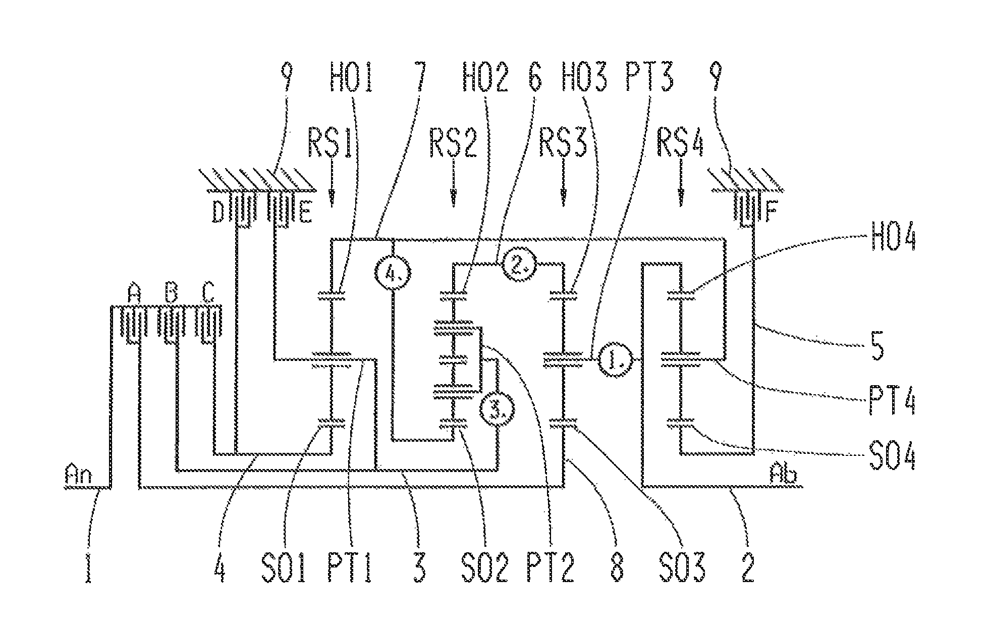
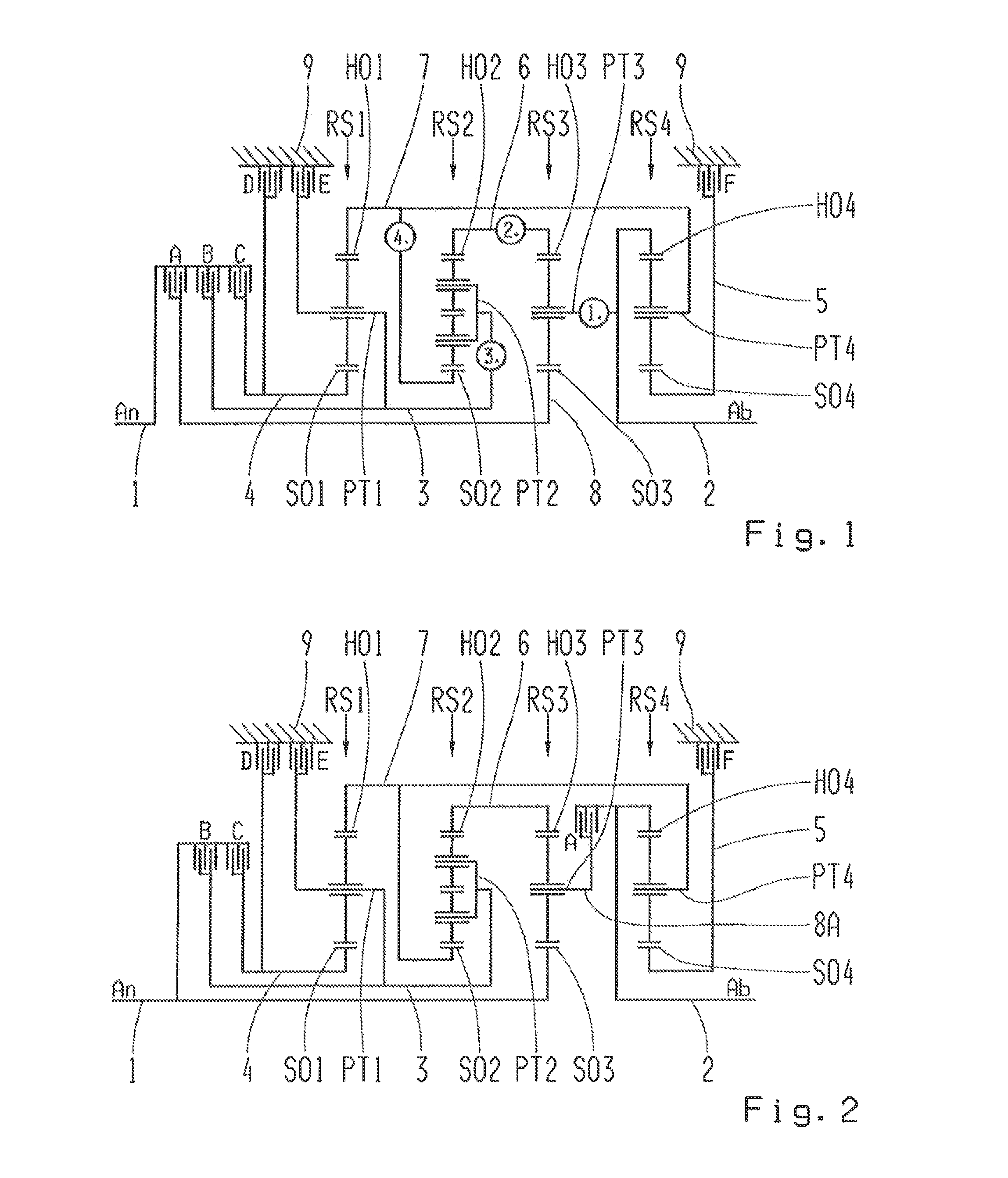
[0032]In the first gear configuration variant of the multi-gear transmission shown in FIG. 1, it is provided that the first shaft 1 can be connected by the first shifting element A in the form of a clutch and by way of the eighth shaft 8 to the sun gear SO3 of the third planetary gearset RS3, which means that the first shaft 1 is detachably connected to the sun gear SO3. Furthermore, the first shaft 1 can be connected or is detachably connected by the second shifting element B in the form of a clutch and by way of the third shaft 3 to the planetary carrier PT1 of the first planetary gearset RS1 and to the planetary carrier PT2 of the second planetary gearset RS2, whereas the planetary carrier PT1 of the first planetary gearset RS1 is detachably connected to the housing 9 by way of the third shaft 3 and by the fifth shifting element E in the form of a brake. In addition, the first shaft 1 is detachably connected to the sun gear SO1 of the first planetary gearset RS1 by the third shi...

second embodiment

[0033]In the gear configuration shown in FIG. 2 variant of the multi-gear transmission, it is provided that the first shaft 1 is connected to the sun gear SO3 of the third planetary gearset RS3. Moreover, the first shaft 1 is connected or can be detachably connected to the planetary carrier PT1 of the first planetary gearset RS1 and to the planetary carrier PT2 of the second planetary gearset RS2 by the second shifting element B in the form of a clutch and by way of the third shaft 3, whereas the planetary carrier PT1 of the first planetary gearset RS1 is detachably connected by way of the third shaft 3 and by the fifth shifting element E in the form of a brake to the housing 9. Furthermore, the first shaft 1 is detachably connected by the third shifting element C in the form of a clutch and by way of the fourth shaft 4 to the sun gear SO1 of the first planetary gearset RS1, whereas the sun gear SO1 of the first planetary gearset RS1 is detachably connected by way of the fourth sha...

third embodiment

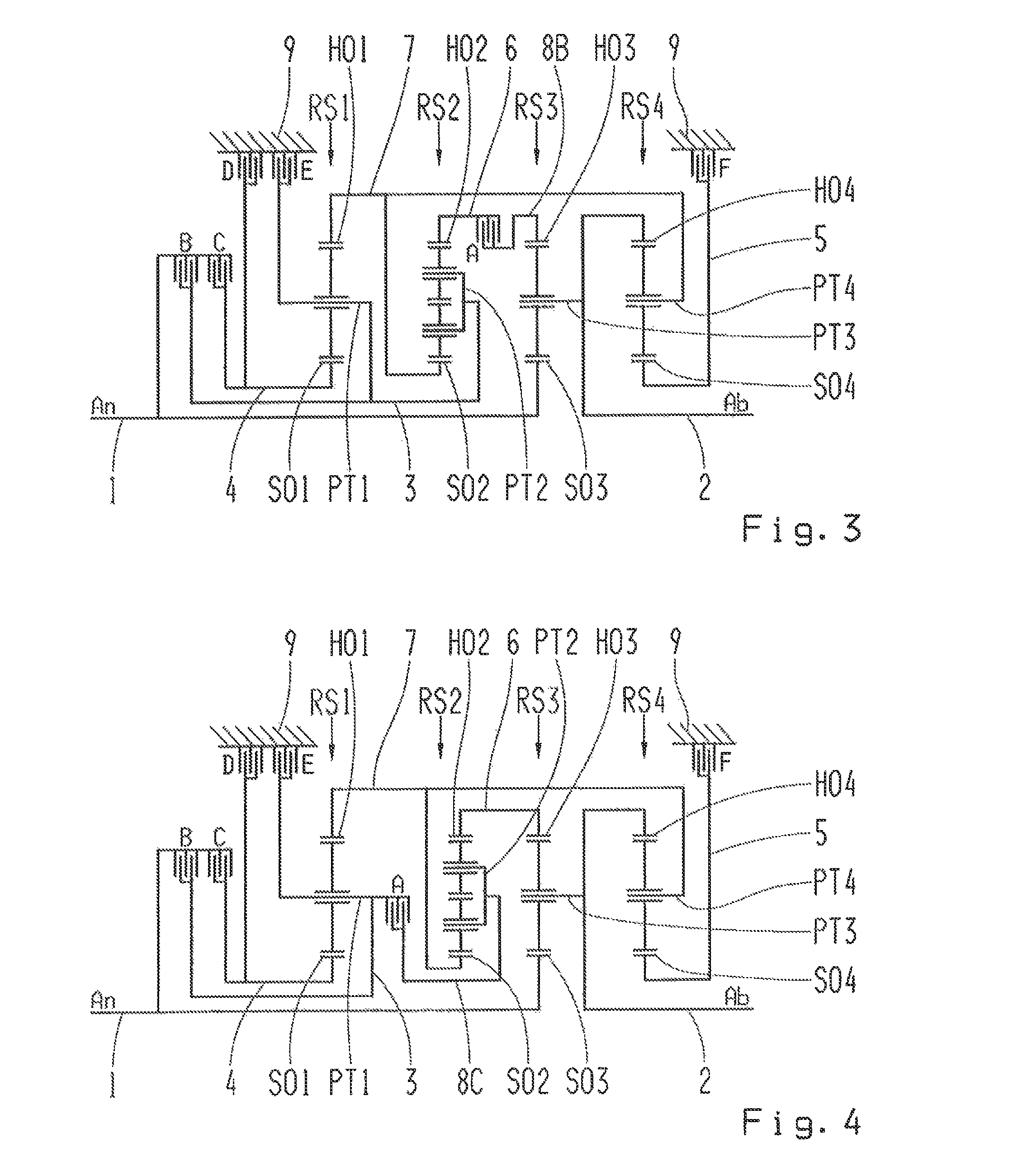
[0034]In the gear configuration shown in FIG. 3 variant of the multi-gear transmission, it is provided that the first shaft 1 is connected to the sun gear SO3 of the third planetary gearset RS3. Moreover, the first shaft 1 is detachably connected by the second shifting element B in the form of a clutch and by way of the third shaft 3 to the planetary carrier PT1 of the first planetary gearset RS1 and to the planetary carrier PT2 of the second gearset RS2, whereas the planetary carrier PT1 of the first planetary gearset RS1 is detachably connected by way of the third shaft 3 and by the fifth shifting element E in the form of a brake to the housing 9. Furthermore, the first shaft 1 is detachably connected by the third shifting element C in the form of a clutch and by way of the fourth shaft 4 to the sun gear SO1 of the first planetary gearset RS1, whereas the sun gear SO1 of the first planetary gearset RS1 is detachably connected by way of the fourth shaft 4 and by the fourth shiftin...


PUM


Abstract

A multi-gear transmission of a vehicle having a housing in which four planetary gearsets and a plurality of shafts and shifting elements are arranged. The drive input shaft can couple the sun gears of gearsets (RS1, RS3) and the carrier of gearset (RS1) and can be connected indirectly to the carrier of gearset (RS2). The drive output shaft couples the ring gear of gearset (RS4) and is connected directly or can be indirectly connected to the carrier of gearset (RS3), the sun gear and carrier of gearset (RS1) and the sun gear of gearset (RS4) can be connected to the housing. The ring gear of gearset (RS1) couples the carrier of gearset (RS4) and can be or is connected to the sun gear of gearset (RS2), and the ring gear of gearset (RS2) and the ring gear of gearset (RS3) are, or can be, connected to one another.

Description

[0001]This application is a National Stage completion of PCT / EP2013 / 050357 filed Jan. 10, 2013, which claims priority from German patent application serial no. 10 2012 203 069.7 filed Feb. 29, 2012.FIELD OF THE INVENTION[0002]The present invention concerns a multi-gear transmission of planetary design for a vehicle.BACKGROUND OF THE INVENTION[0003]From the document U.S. Pat. No. 7,887,453 B2 a multi-gear planetary transmission for a vehicle is known. The multi-gear transmission comprises four planetary gearsets and six shifting elements, so that nine forward gears and one reverse gear are produced. From the shifting scheme of the known multi-gear transmission it is apparent that to obtain each gear, in each case only two of the shifting elements are closed. Thus, owing to the open disk shifting elements undesired drag losses occur.[0004]Furthermore, it is known to be advantageous for shifting elements to be easily accessible, for example positioned externally, so that the hydraulic ...

Claims


Application Information

Patent Timeline
Patent Type & Authority Patents(United States)
IPC IPC(8): F16H3/62
CPCF16H3/62F16H2200/0065F16H2200/2012F16H2200/2046F16H3/666F16H2200/0069
Inventor BECK, STEFANSIBLA, CHRISTIANRIEGER, WOLFGANG
Owner ZF FRIEDRICHSHAFEN AG
Why Eureka
Try Eureka