Optical transmitter implemented with two QPSK modulators made of semiconductor material and a method to control optical power output therefrom

a technology of semiconductor material and optical power output, which is applied in the direction of transmission monitoring/testing/fault-measurement systems, transmission monitoring, electrical equipment, etc., can solve the problems that the optical power output of the conventional dp-qpsk modulator is extremely difficult to control

Active Publication Date: 2015-11-24
SUMITOMO ELECTRIC IND LTD
View PDF6 Cites 3 Cited by
  • Summary
  • Abstract
  • Description
  • Claims
  • Application Information

AI Technical Summary

Benefits of technology

[0006]One aspect according to an embodiment of the present application relates to an optical transmitter implemented with two QPSK modulators, one is for the X-polarization and the other is for the Y-polarization. Each of QPSK modulators outputs an optical signal and includes a waveguide made of semiconductor material showing the Quantum Confined Stark Effect (QCSE). The waveguide accompanies with an electrode to receive a bias supplied thereto. The optical transmitter of the embodiment further provides a power controller. The power controller provides a bias to the electrode of the waveguide in one of the QPSK modulators to eliminate the optical output derived from the other of the QPSK modulator. Thus, the contribution of the optical signals each output from the QPSK modulators to the output of the optical transmitter is controlled precisely and easily.

Problems solved by technology

Various techniques to even the contribution have been proposed; however, conventional DP-QPSK modulators have been extremely hard to control the optical power output therefrom in precisely, in particular, the contribution of two QPSK modulators to the optical output power.

Method used


Image

  • Optical transmitter implemented with two QPSK modulators made of semiconductor material and a method to control optical power output therefrom
  • Optical transmitter implemented with two QPSK modulators made of semiconductor material and a method to control optical power output therefrom
  • Optical transmitter implemented with two QPSK modulators made of semiconductor material and a method to control optical power output therefrom

Examples


Embodiment Construction

[0018]Next, some preferred embodiments according to the present invention will be described in detail as referring to drawings. In the description of the drawings, the numerals or symbols same or similar to each other will refer to the elements same or similar to each other without overlapping explanations.

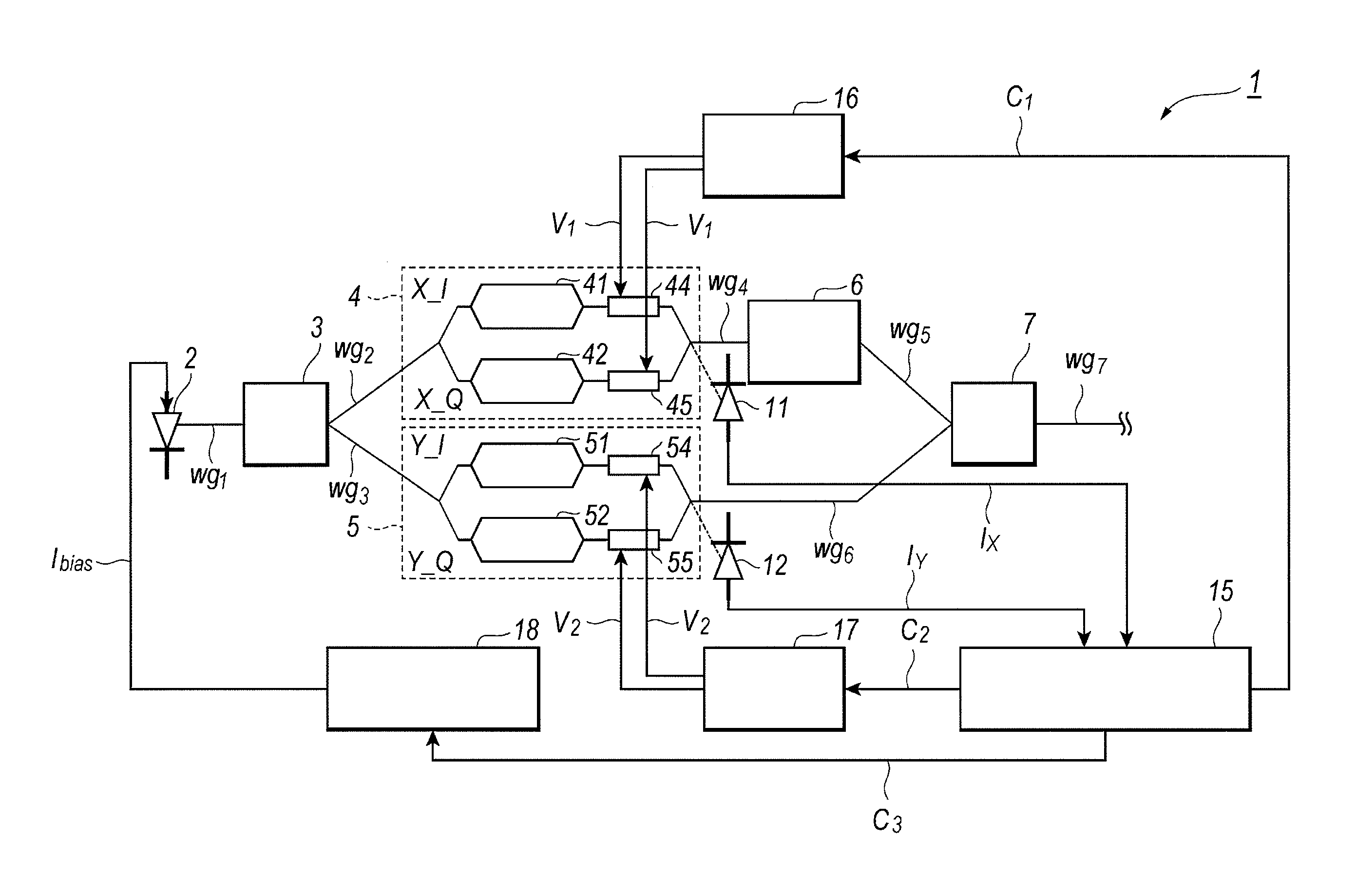
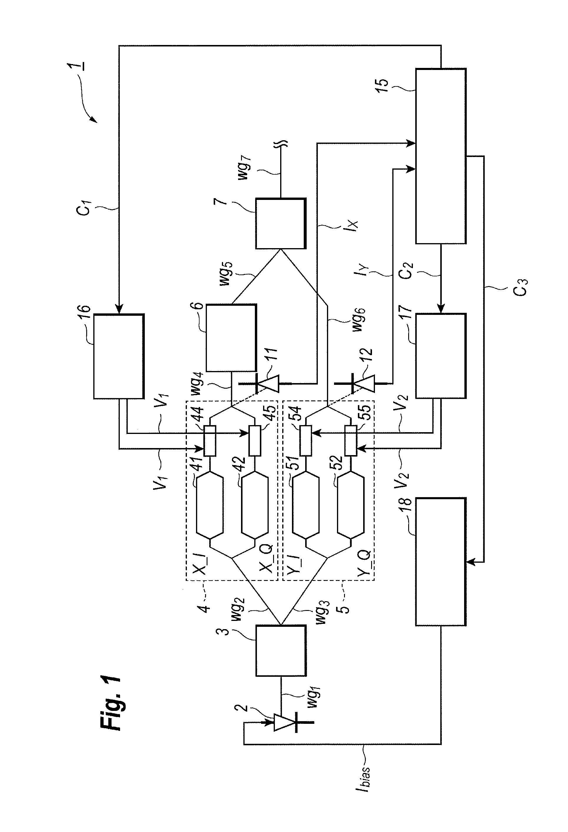
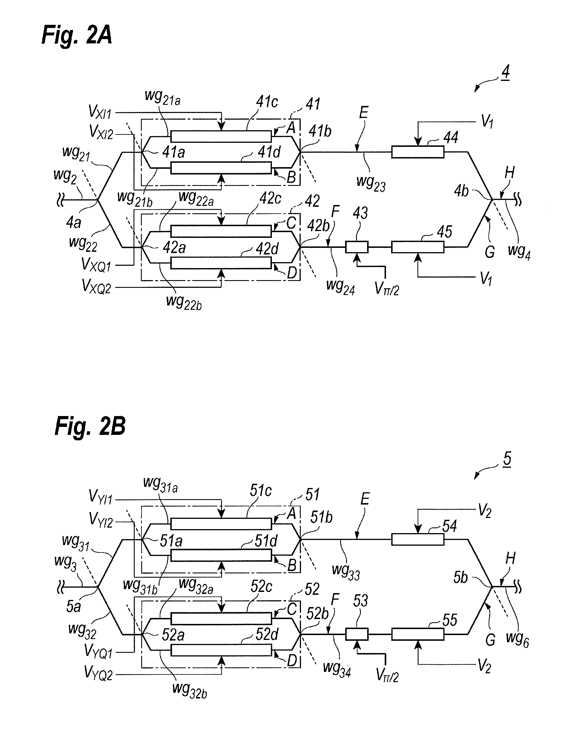
[0019]FIG. 1 schematically illustrates an optical transmitter 1 including semiconductor optical modulators, 4 and 5. The optical transmitter 1, which is the type of the DP-QPSK (Dual Polarization Quadrature Phase Shift Keying), generates the optical signal containing first and second modulated signals with polarizations perpendicular to each other, where they are denoted as the X-polarization and Y-polarization in this specification. The optical transmitter 1 includes light source 2, a beam splitter 3, first and second QPSK modulators, 4 and 5, a polarization rotator 6, a polarization multiplexer 7, first and a second power monitors, 11 and 12, a power controller 15, two power sup...


PUM


Abstract

An optical transmitter implemented with two QPSK (Quadrature Phase Shift Keying) modulators is disclosed. Each of the QPSK modulators provides a waveguide made of semiconductor material inducing the QCSE (Quantum Confined Stark Effect) by a bias supplied thereto. The optical performance of one of the QPSK modulators is determined by supplying a deep bias to the other of the QPSK modulator to eliminate the optical output therefrom.

Description

BACKGROUND OF THE INVENTION[0001]1. Field of the Invention[0002]The present invention relates to a semiconductor optical modulator and a method to control optical power output from the same.[0003]2. Related Background Art[0004]The optical communication system using the phase modulation, which drastically enhances the spectrum efficiency, has been proposed. Among the phase modulation techniques, the quadrature phase shift keying (QPSK) combined with the polarization multiplexing, which is called, as the Dual Polarization-Quadrature Phase Shift Keying (DP-QPSK) has been a promising technique.[0005]The DP-QPSK mode requires the even contribution of respective QPSK modulators, one is for X-polarization and the other is for Y-polarization, to the optical power output from the DP-QPSK transmitter. Various techniques to even the contribution have been proposed; however, conventional DP-QPSK modulators have been extremely hard to control the optical power output therefrom in precisely, in p...

Claims


Application Information

Patent Timeline
Patent Type & Authority Patents(United States)
IPC IPC(8): H04B10/50H04B17/00H04B10/548H04B10/556
CPCH04B10/548H04B10/5053H04B10/5561
Inventor YAMANAKA, SHINGO
Owner SUMITOMO ELECTRIC IND LTD
Why Eureka
Try Eureka