Motorized air walker and suspension system for paralyzed persons

a technology of paralyzed persons and air walker, which is applied in the field of apparatus and methods for gait rehabilitation, can solve the problems of affecting the life of those suffering from such a condition, affecting the rehabilitation of patients, and requiring significant effort from the clinician, so as to improve the rehabilitation effect, increase or, and accommodate the gait of the patien

Active Publication Date: 2016-08-23
KALINOWSKI EUGENE
View PDF34 Cites 4 Cited by
  • Summary
  • Abstract
  • Description
  • Claims
  • Application Information

AI Technical Summary

Benefits of technology

[0044]The gripping portion of each of the pair of legs may be selectively adjustable in height. Selective adjustment of the height of the gripping portion of each of the pair of legs may increase or decrease the stroke of the pair of legs of the walker in order to accommodate a gait of the patient.

Problems solved by technology

Such injuries, as well neurological disorders, can have a devastating effect on the lives of those suffering from such an affliction, especially those who are young.
While this sufficiently unloads the patient's legs and maintains the body position of the patient, significant effort is required by the clinician to guide the patient into the harness and into an appropriate position within the machine.
This type of system often places considerable strain on the therapist.
Additionally, it is difficult to maintain consistent gait as locomotion is effectuated manually by the clinician.
An additional limitation is the gait of the clinician is often mismatched with that of the patient due to differing body sizes.
While this type of system eliminates some of the previously disclosed issues, significant limitations still remain.
Additionally, significant effort is required to secure and adjust the driven gait orthosis to the patient.
Moreover, a limitation of both disclosed systems is the patient being a passive part of the system, i.e. effectuation of the movement of the legs is by means of external forces.

Method used


Image

  • Motorized air walker and suspension system for paralyzed persons
  • Motorized air walker and suspension system for paralyzed persons
  • Motorized air walker and suspension system for paralyzed persons

Examples


Embodiment Construction

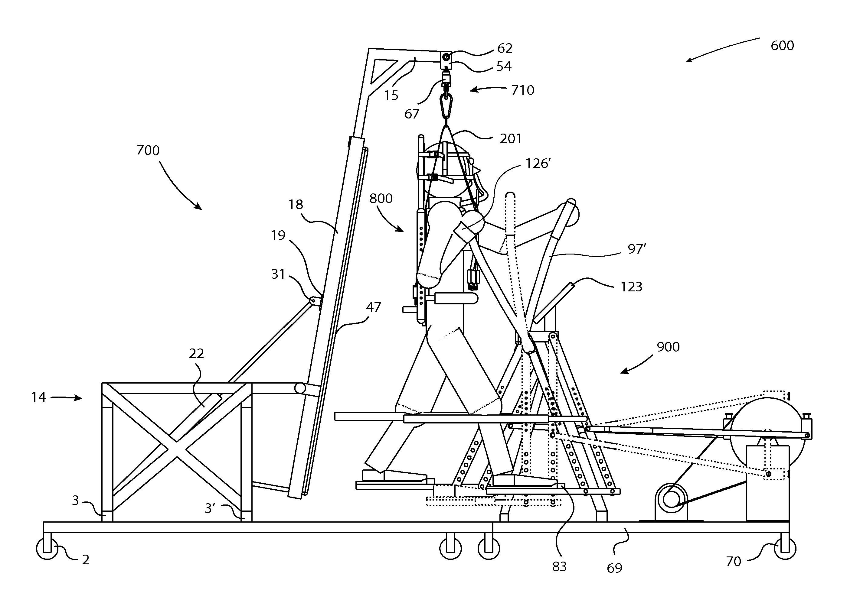
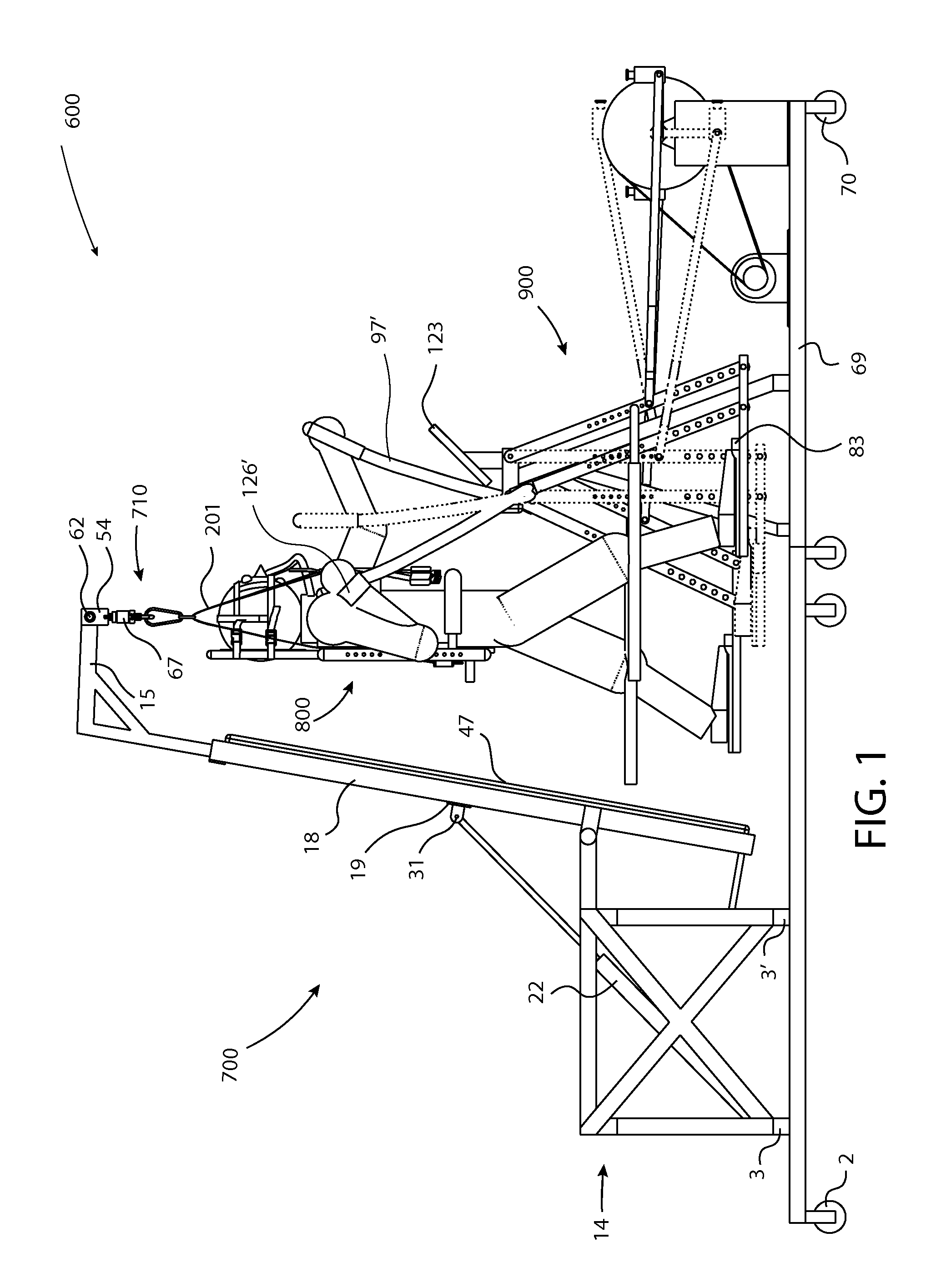
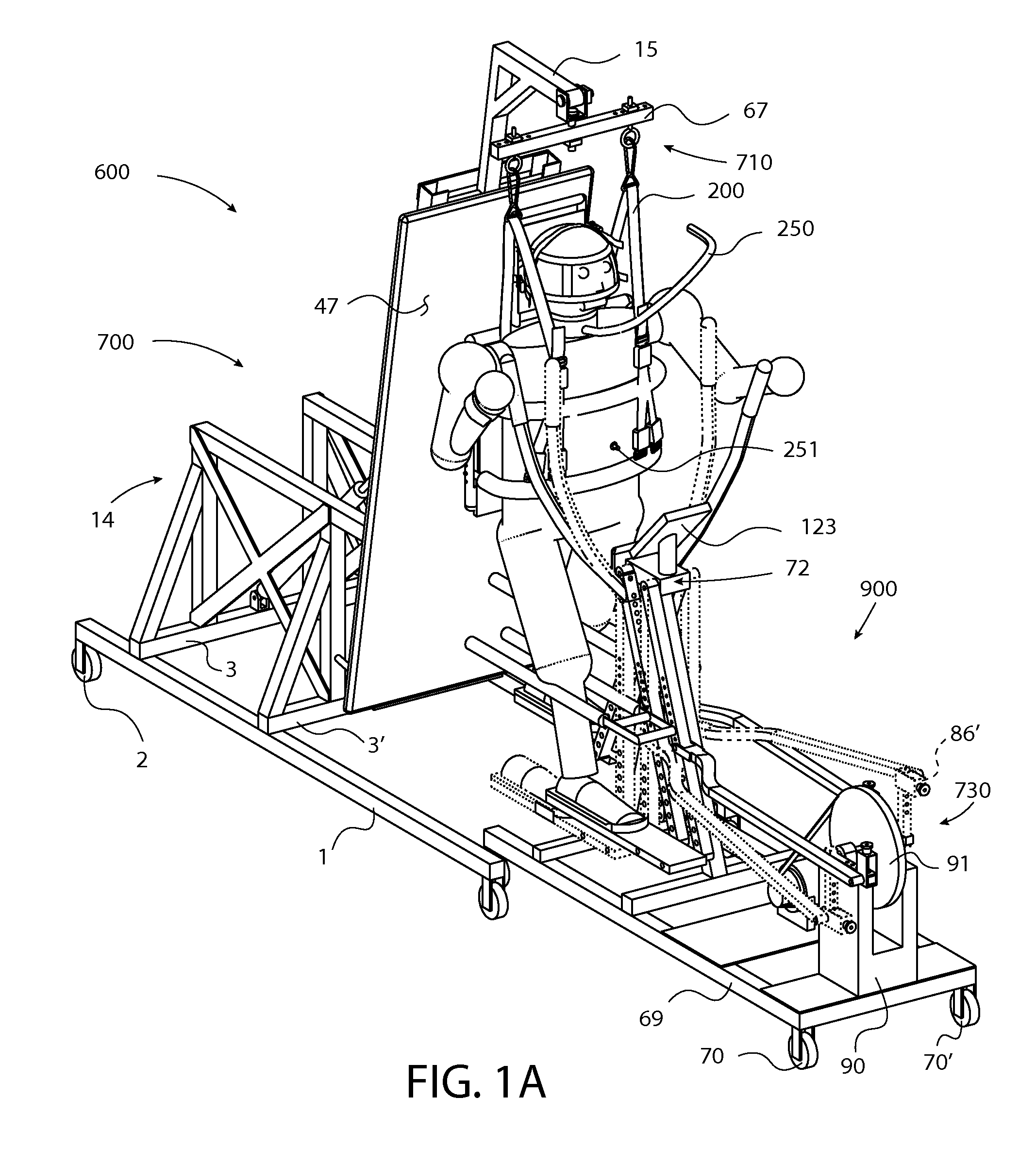
[0085]Embodiments of the present disclosure are now described in detail with reference to the drawings in which like reference numerals designate identical or corresponding elements in each of the several views. As used herein, the term “clinician” refers to a doctor, a nurse or any other care provider and may include support personnel. Additionally, the term “person” refers to a patient. The term “proximal” will refer to the portion of the device, component, or patient thereof that is closer to the clinician and the term “distal” will refer to the portion of the device, component, or patient thereof that is farther from the clinician. The term “cephalic” will refer to the portion of the device, component, or portion of the body of a patient that is towards the head of the patient and the term “caudal” will refer to the portion of the device, component, or portion of the body of a patient that is towards the feet of the patient. Additionally, in the drawings and in the description t...


PUM


Abstract

A system for patient rehabilitation is disclosed. The system includes a first movable frame including an articulating bed, wherein the bed is configured to be selectively articulated to an inclined position, a suspension system, wherein the suspension system is disposed within the articulating bed and is selectively adjustable to accommodate varying patient height, a harness, wherein the harness is selectively engageable with the suspension system, wherein the harness is selectively adjustable to accommodate varying patient sizes, a second movable frame including a walker, wherein the walker includes a pair of legs and a motor, wherein approximation of the two movable frames permits the patient to easily utilize the walker from the bed. A method of using the system for patient rehabilitation is also disclosed.

Description

CROSS-REFERENCE TO RELATED APPLICATION[0001]This application claims priority to, and the benefit of, U.S. Provisional Patent Application No. 61 / 967,016, filed on Mar. 7, 2014, the entire contents of which are hereby incorporated by reference herein.BACKGROUND[0002]1. Technical Field[0003]The present disclosure relates generally to apparatus and methods for gait rehabilitation and, in particular, to an apparatus for locomotor therapy and method of operating the same.[0004]2. Background of the Disclosure[0005]Spinal cord injuries affect approximately 12,000 individuals within the United States each year. Such injuries, as well neurological disorders, can have a devastating effect on the lives of those suffering from such an affliction, especially those who are young. Recent innovations in the area of gait rehabilitation have explored the use of locomotor therapy for those suffering from stroke, spinal cord injury, Parkinson's disease, cerebral palsy, traumatic brain injury, and the li...

Claims


Application Information

Patent Timeline
Patent Type & Authority Patents(United States)
IPC IPC(8): A61H3/00A61H1/02
CPCA61H3/008A63B21/4007A61H2003/007A61H2001/0211A61H1/0237A61H1/0274A61H1/0262A61H2201/0142A61H2201/0157A61H2201/10A61H2201/107A61H2201/1215A61H2201/1642A61H2201/1652A61H2201/50A61H2201/5046A61H2201/5048A61H2201/5064A61H2203/0406A61H2201/1614A61H2201/1409A61H2201/1607A61H2201/1621A61H2201/1638A61H2201/1481A63B21/4034A63B21/4035A61G7/018A61G7/1046A61G7/1051A63B21/225A63B22/001A63B22/0023A63B22/0664A63B23/03575A63B2022/0676
Inventor KALINOWSKI, EUGENE
Owner KALINOWSKI EUGENE
Why Eureka
Try Eureka