Gas turbine and operation method of gas turbine

a gas turbine and gas turbine technology, applied in the direction of engines, mechanical equipment, machines/engines, etc., can solve the problems of reduced compressor reliability, increased vane load, reduced compressor reliability, etc., and achieve the effect of suppressing the reduction of compressor reliability

Active Publication Date: 2018-01-09
MITSUBISHI POWER LTD
View PDF14 Cites 0 Cited by
  • Summary
  • Abstract
  • Description
  • Claims
  • Application Information

AI Technical Summary

Benefits of technology

The invention relates to a gas turbine and its operation method that can prevent the decrease in the compressor's reliability caused by changes in the steam injection rate, temperature, or inlet guide vane opening.

Problems solved by technology

Therefore, the reduction in the compressor reliability becomes a problem such that the pressure ratio per each vane stage of the compressor increases and the vane load of the compressor increases, thus there is a risk that an unstable phenomenon such as surging may be caused.
Therefore, similarly, the reduction in the compressor reliability comes into a problem.
Therefore, depending on the stage of the compressor, the vane load increases and a risk of generation of an unstable phenomenon such as surging may be increased.
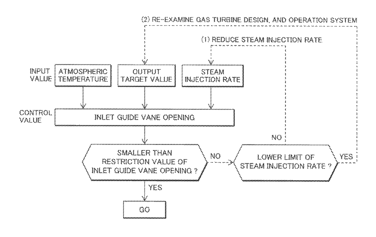
As mentioned above, in the gas turbine with the combustor injected with steam, under the conditions of the atmospheric temperature, if the inlet guide vane opening and the steam injection rate are not appropriate, there is a risk of an extreme reduction in the compressor reliability.

Method used

the structure of the environmentally friendly knitted fabric provided by the present invention; figure 2 Flow chart of the yarn wrapping machine for environmentally friendly knitted fabrics and storage devices; image 3 Is the parameter map of the yarn covering machine
View more

Image

Smart Image Click on the blue labels to locate them in the text.
Viewing Examples
Smart Image
  • Gas turbine and operation method of gas turbine
  • Gas turbine and operation method of gas turbine
  • Gas turbine and operation method of gas turbine

Examples

Experimental program
Comparison scheme
Effect test

embodiment 1

[0037]A preferable embodiment of the present invention will be explained below by referring to the drawings. FIG. 1 is a schematic block diagram showing the gas turbine facilities structured using the steam injection gas turbine relating to a first embodiment of the present invention. The gas turbine of the first embodiment includes a rotor 5, a compressor 1 for compressing air, inlet guide vanes 6 installed at the stages near the compressor inlet, an inlet guide vane opening monitoring mechanism 21 for monitoring the opening of the inlet guide vanes 6, an inlet guide vane adjustment mechanism 22 for adjusting the opening of the inlet guide vanes 6, a combustor 2 for taking in compressed air, mixing it with fuel, and burning them, a turbine 3 for converting the combustion energy to the drive force of the rotor 5, a generator 4 for converting the rotation drive force of the rotor 5 to electricity, a steam feed system 7 for feeding steam to the combustor 2, an pressure regulation valv...

embodiment 2

[0053]A second embodiment of the present invention will be explained below by referring to FIGS. 1 and 6. The gas turbine of the second embodiment, as shown in FIG. 1, includes the rotor 5, the compressor 1 for compressing air, the inlet guide vanes 6 installed at the stages near the compressor inlet, the inlet guide vane opening monitoring mechanism 21 for monitoring the inlet guide vane opening, the inlet guide vane adjustment mechanism 22 for adjusting the inlet guide vane opening, the combustor 2 for taking in compressed air, mixing it with the fuel 18, and burning them, the turbine 3 for converting the combustion energy to the drive force of the rotor 5, the generator 4 for converting the rotation drive force of the rotor 5 to electricity, the steam feed system 7 for feeding steam to the combustor 2, the pressure regulation valve 9 for adjusting the steam injection rate, the steam rate adjustment mechanism 8 for adjusting the opening of the pressure regulation valve 9, the stea...

embodiment 3

[0064]A third embodiment of the present invention will be explained below by referring to FIGS. 1, 8 and 9. The gas turbine of the third embodiment includes the rotor 5, the compressor 1 for compressing air, the inlet guide vanes 6 installed at the stages near the inlet of the compressor 1, the inlet guide vane opening monitoring mechanism 21 for monitoring the opening of the inlet guide vanes 6, the inlet guide vane adjustment mechanism 22 for adjusting the inlet guide vane opening, the combustor 2 for taking in compressed air, mixing it with the fuel 18, and burning them, a fuel adjustment mechanism 25 for adjusting fuel, a combustion temperature monitoring mechanism 26 for monitoring the combustion temperature, a pressure ratio monitoring mechanism 27 for measuring a pressure of the compressed air discharged from the compressor 1, the turbine 3 for converting the combustion energy to the drive force of the rotor 5, the generator 4 for converting the rotation drive force of the ro...

the structure of the environmentally friendly knitted fabric provided by the present invention; figure 2 Flow chart of the yarn wrapping machine for environmentally friendly knitted fabrics and storage devices; image 3 Is the parameter map of the yarn covering machine
Login to View More

PUM

No PUM Login to View More

Abstract

A gas turbine having a compressor for compressing air, a combustor for taking in compressed air discharged from the compressor, mixing it with fuel, and burning them, and a turbine driven by combustion gas generated in the combustor, comprising: inlet guide vanes installed at a stage near an inlet of the compressor for adjusting a compressor flow rate by changing an attaching angle thereof, a steam injection mechanism for injecting steam to the combustor, a steam adjustment valve for adjusting the steam injection rate, and a steam rate control mechanism for adjusting an opening of the steam adjustment valve, a steam monitoring mechanism for monitoring the steam rate injected to the combustor, an air temperature monitoring mechanism for monitoring an atmospheric temperature, and a control unit for determining whether a restriction value of the steam injection rate using a temperature, an opening of the inlet guide vanes, and the steam injection rate as indexes is satisfied, and controlling at least one of a temperature of air flowing into the compressor, the steam injection rate, and the inlet guide vane opening.

Description

[0001]The present application claims priority from Japanese patent application JP 2012-251767 filed on Nov. 16, 2012, the content of which is hereby incorporated by reference into this application.BACKGROUND OF THE INVENTION[0002]Field of the Invention[0003]The present invention relates to a steam or inert gas injection gas turbine for injecting steam or inert gas to a combustor and a control method therefor and more particularly to an operation method of a gas turbine compressor.[0004]Description of Related Art[0005]In high-efficiency realization and high-output realization of a power generation gas turbine, the combustion temperature of the combustor needs realization of high temperature, however, in correspondence with a rise of the combustion temperature, the generation rate of NOx increases exponentially. NOx is generated in a portion locally raised in temperature by a diffusion flame, so that a method of injecting steam into the combustor, thereby lowering the combustion tempe...

Claims

the structure of the environmentally friendly knitted fabric provided by the present invention; figure 2 Flow chart of the yarn wrapping machine for environmentally friendly knitted fabrics and storage devices; image 3 Is the parameter map of the yarn covering machine
Login to View More

Application Information

Patent Timeline
no application Login to View More
Patent Type & AuthorityPatents(United States)
IPC IPC(8): F02C3/30F01K21/04F02C9/20F01D17/16
CPCF02C3/30F01D17/16F01K21/047F02C9/20Y02E20/16F05D2270/082F05D2270/101F05D2270/16Y02E20/14F05D2260/2322
InventorTAKEDA, HIROKIAKIYAMA, RYOTAKAHASHI, YASUO
OwnerMITSUBISHI POWER LTD