Two-circuit injector for a turbine engine combustion chamber

a turbine engine and combustion chamber technology, applied in the direction of machines/engines, combustion types, lighting and heating apparatus, etc., can solve the problems of engine embrittlement, engine restart, engine start or restart,

Active Publication Date: 2018-03-27
SAFRAN HELICOPTER ENGINES
View PDF14 Cites 15 Cited by
  • Summary
  • Abstract
  • Description
  • Claims
  • Application Information

AI Technical Summary

Benefits of technology

[0016]Another aim of the invention is to enable faster ignition of the combustion chamber and which is accordingly more economical in fuel.
[0037]With the fuel ignition circuit being arranged in an enclosure, the injector is much less exposed to the phenomenon of blowing as the enclosure acts as a pre-combustion chamber whereof the walls confine the air. Ignition of the fuel is therefore faster and considerably reduces the consumption of fuel at start-up.
[0038]Also, protection against blowing can start up or restart up the combustion chamber even when the latter has just stopped without the engine having to have slowed to 20% of its capacity.
[0039]Due to its principal start-up circuit, the injector has a greater rate of fuel than a traditional start-up injector. This rate ignites a greater proportion of the combustion chamber, and therefore reduces the number of injectors to be used and ignited at the same time. The turbine engine is ignited, and is therefore less expensive to produce and more economical in fuel.

Problems solved by technology

Conventional start-up injectors have some disadvantages, including a considerable blowing effect, linked to the current of air in the combustion chamber, which prevents start-up or restart-up of the engine since the latter has not slowed to less than 20% of its capacity.
An engine which has just been switched off cannot therefore be restarted immediately.
Engines also become embrittled because of the need for two orifices per injector in the combustion chamber and in the casing due to having an atomizer and a spark plug enter inside the chamber.
This adds weight to the engine and makes it more expensive to produce.
This assembly in the combustion chamber does not correct the blowing effect, since in particular the start-up injector is exposed to the air flow of the combustion chamber.
As a consequence, in case of high engine speed, it is not possible to start up ignition of the fuel.

Method used


Image

  • Two-circuit injector for a turbine engine combustion chamber
  • Two-circuit injector for a turbine engine combustion chamber
  • Two-circuit injector for a turbine engine combustion chamber

Examples


Embodiment Construction

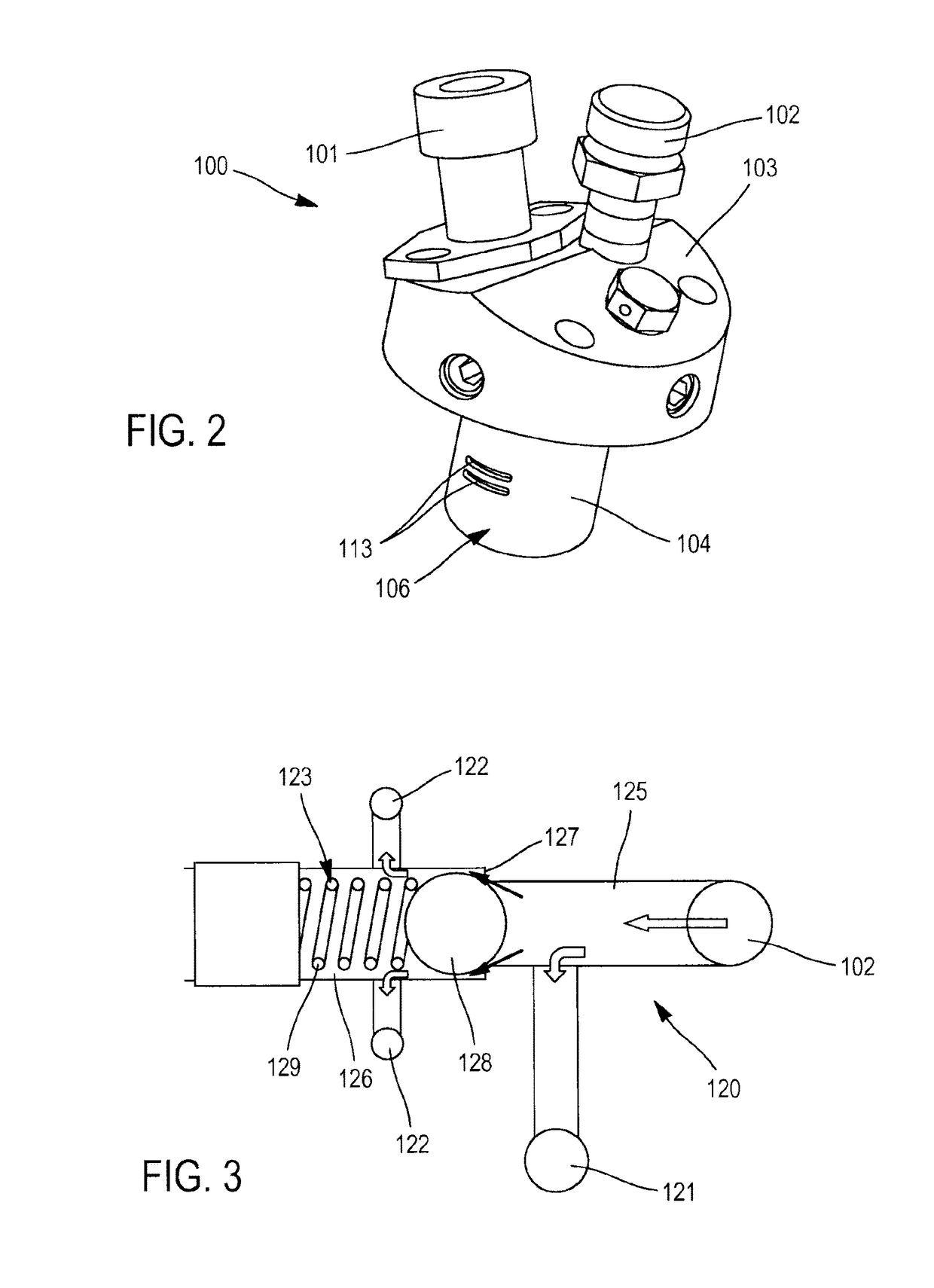
[0049]In reference to FIG. 2, this illustrates a start-up injector 100 of a combustion chamber of a turbine engine. It comprises a fuel ignition spark plug 101, and a fuel inlet 102.

[0050]The spark plug 101 can be a spark plug, or preferably a glow plug, which has a size reduced relative to the spark plug and decreases the volume of the injector 100.

[0051]In reference to FIG. 3, the injector 100 comprises a fuel injection circuit 120 in fluid communication with the fuel inlet 102, and with two circuits 130 and 140 intended to ignite the combustion chamber.

[0052]With reference again to FIG. 2, the fuel injection circuit is arranged in a hood 103 of the injector, intended to be fixed on the casing 30 of a turbine engine 1, for example by bolting.

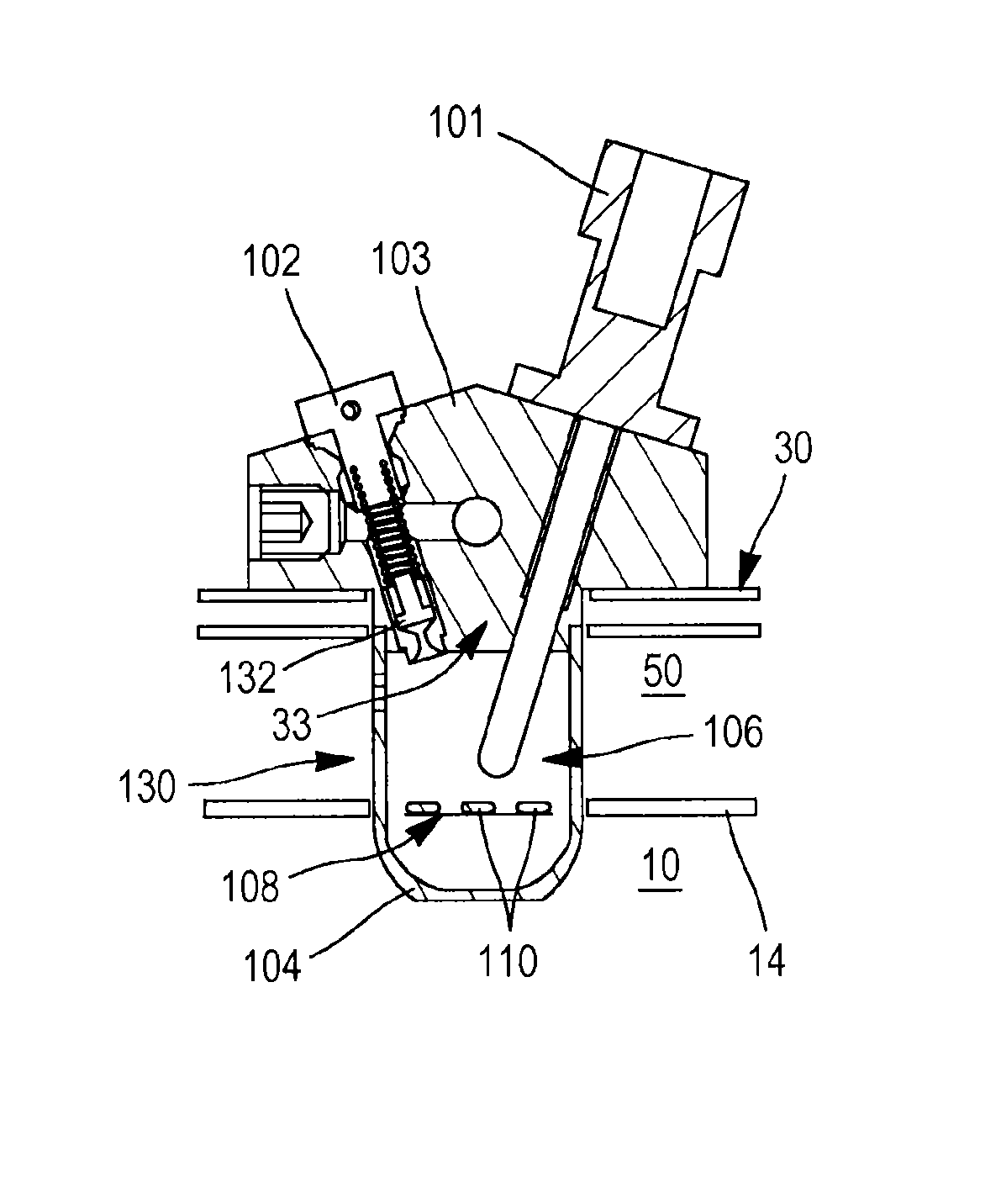
[0053]An enclosure 104, wherein ignition of the fuel takes place before the latter enters the combustion chamber, projects from the hood 103. As is evident in FIGS. 4a to 4c, the injector is attached to the casing 30 such that this enclosure 1...


PUM


Abstract

A start-up injector for a turbine engine combustion chamber, said injector including a fuel injection circuit; and a fuel ignition circuit including a fuel injector supplied by the fuel injection circuit and a spark plug for igniting the injected fuel. The start-up injector also includes a partitioned enclosure including a first compartment in which the fuel is ignited by the spark plug and a second compartment separated from the first compartment by a thermally conductive partition; and a main combustion start-up circuit which includes at least one fuel injector supplied by the fuel injection circuit and opens into the second compartment of the enclosure such as to inject the fuel against the wall.

Description

FIELD OF THE INVENTION[0001]The field of the invention is that of combustion chamber injectors of turbine engines, especially combustion start-up injectors.[0002]The invention also relates to turbine engines fitted with such injectors.PRIOR ART[0003]In reference to FIG. 1, turbine engines 1 conventionally comprise a combustion chamber 10 and a distributor 20 housed in a casing 30, the combustion chamber being delimited by external 14 and internal 12 walls of revolution, one extending inside the other and being connected by an annular bottom wall 16 of the chamber.[0004]The casing also has an internal wall 32 and an external wall 31 to which the internal 12 and external walls of the combustion chamber are respectively fixed.[0005]A mix of air and fuel is injected into the combustion chamber by a plurality of injectors 18 mounted on the chamber bottom wall, and distributed over the entire circumference of the latter.[0006]Several types of injectors are arranged in a combustion chamber...

Claims


Application Information

Patent Timeline
Patent Type & Authority Patents(United States)
IPC IPC(8): F02C1/00F02C3/14F23D11/44F23R3/34F23R3/30F02C7/264
CPCF23R3/30F02C3/14F23D11/446F23R3/343F02C7/264Y02T50/671Y02T50/60F23R3/28
Inventor CARRERE, BERNARD
Owner SAFRAN HELICOPTER ENGINES
Why Eureka
Try Eureka