
Refrigeration cycle apparatus
一种制冷循环、制冷剂的技术,应用在制冷机、制冷组件、制冷和液化等方向,能够解决上升、性能低下等问题,达到抑制歧化反应、高性能的效果
Patent Information
- Authority / Receiving Office
- CN · China
- Patent Type
- Applications(China)
- Current Assignee / Owner
- Publication Date
- 2016-11-09
Smart Images
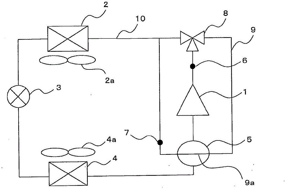
Figure 1 
Figure 2 
Figure 3
Abstract
Description
technical field
[0001] The invention relates to a refrigeration cycle device using a non-azeotropic mixed refrigerant as a working refrigerant. Background technique
[0002] In recent years, in order to suppress the influence on global warming, low-GWP refrigerants have been developed. R410A used in the past is a good refrigerant, but since its GWP (global warming coefficient) is about 2000, R32 with a GWP of about 1 / 3 of R410A is currently being used. R32 is a refrigerant with similar physical properties to R410A and good performance, with a GWP of about 600. In order to further reduce the GWP, fluoroethylene (HFO) refrigerants such as HFO-1234yf are being developed.
[0003] However, this refrigerant is a refrigerant with a high boiling point and low performance. To maintain the same performance as in the past, there are many technical problems, and there is a possibility that the cost will increase.
[0004] Accordingly, a refrigeration cycle device using a refrigerant...
Examples
Embodiment approach 1
[0042] First, the configuration of the refrigeration cycle apparatus in Embodiment 1 will be described.
[0043] figure 1 It is a schematic configuration diagram of the refrigeration cycle apparatus in Embodiment 1.
[0044] like figure 1 As shown, the refrigeration cycle device in Embodiment 1 has a main path that sequentially connects the compressor 1, the condenser 2, the expansion valve 3, the evaporator 4, and the accumulator 5 (corresponding to the gas-liquid separator of the present invention). 10. In addition, the refrigerating cycle device has a bypass path 9 branched from the discharge side of the compressor 1 of the main path 10 , passes through the accumulator 5 via the three-way valve 8 , and communicates with the discharge side of the main path 10 . The inlet side of the condenser 2 is connected. And, these respective structural elements are connected by refrigerant piping.
[0045] In addition, the bypass path 9 and the heat exchange portion 9a of the accum...
Embodiment approach 2
[0090] Next, the structure of the refrigeration cycle apparatus in Embodiment 2 is demonstrated.
[0091] Figure 10 It is a schematic configuration diagram of the refrigeration cycle apparatus in Embodiment 2.
[0092] In the refrigeration cycle apparatus of the second embodiment, the basic structure is the same as that of the first embodiment, but there is a difference in that a four-way valve 11 is provided on the downstream side of the three-way valve 8, and the flow direction of the refrigerant can be switched, Therefore, only this point will be described. In addition, the same reference numerals are assigned to the same constituent elements as in Embodiment 1 (in Embodiment 1, the heat exchanger is divided into a condenser 2 and an evaporator 4, and in Embodiment 2, by switching the four-way valve 11, the condenser 2 can sometimes function as an evaporator, and evaporator 4 can sometimes function as a condenser).
[0093] Next, the operation of the refrigeration cycle...
Embodiment approach 3
[0103] Next, the structure of the refrigeration cycle apparatus in Embodiment 3 is demonstrated.
[0104] Figure 13 It is a schematic configuration diagram of the refrigeration cycle apparatus in Embodiment 3.
[0105] In the refrigeration cycle apparatus in Embodiment 3, the basic configuration is the same as in Embodiment 1, but in the initial state of starting the operation, the discharge refrigerant of the compressor 1 is supplied to the accumulator 5, There is also a compressor heating mechanism 13 and an accumulator heating unit 14 in places where the refrigerant tends to accumulate when the compressor 1 and the accumulator 5 are stopped, and they are different in that they can be heated.
[0106] As the compressor heating mechanism 13 , for example, a heating mechanism that heats the compressor 1 by energizing (constrained energization) the motor coil without driving the motor inside the compressor 1 can be used, for example.
[0107] In addition, the outer surface o...