
3D imaging device for surgical microscopes
A technology of an operating microscope and an imaging device, applied in the field of medical devices, can solve the problems of high requirements for research and development and manufacturing, no three-dimensional effect, etc., and achieve the effect of simple structure and convenient use.
Patent Information
- Authority / Receiving Office
- CN · China
- Patent Type
- Applications(China)
- Current Assignee / Owner
- Publication Date
- 2017-09-05
Smart Images

Figure 1 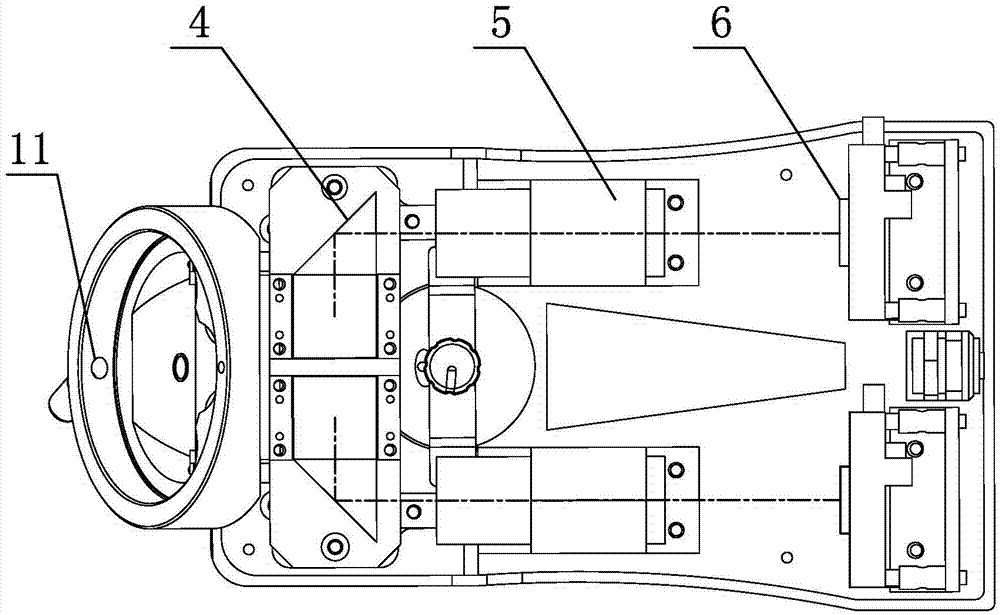
Figure 2 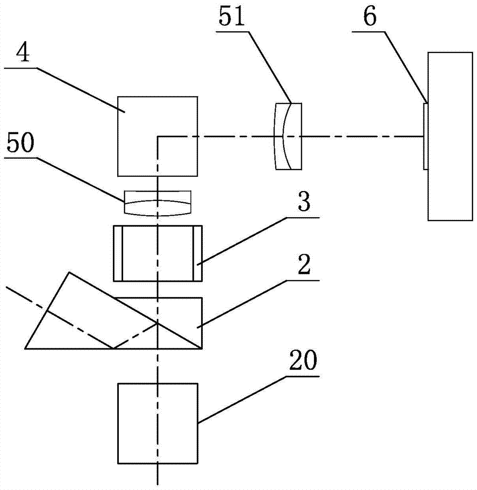
Figure 3
Abstract
Description
technical field
[0001] The present invention relates to the field of medical equipment, in particular to an operating microscope 3D imaging device 。 Background technique
[0002] The most important function of human vision is to generate perception of depth through the difference in parallax between the left and right eyes. Traditional video and film and television systems only focus on the transmission and display of flat images. Although monocular flat images can also produce stereoscopic perception such as occlusion effects, depth of motion, relative size of objects and shadows. But the real stereoscopic effect can only be produced in stereoscopic video.
[0003] When the human eye is watching a scene, the two eyes are separated by a certain distance, and they perceive the object from two different angles, and there are subtle differences between the left and right eye images. This difference can help the human brain to synthesize a complete three-dimensional...
Examples
Embodiment 1
[0029] as shown in the picture 1 、 2 an operating microscope 3D Imaging device, including housing 1 ,case 1 There is a mirror body connection part connected with the main mirror body 10 , the lens barrel connecting part connected with the binocular tube 11 。
[0030] in the shell 1 Built-in beam splitter 2 , variable aperture 3 , left and right steering mirror group 4 , left and right imaging mirror groups 5 and left and right photosensitive elements 6 . Where: Iris diaphragm 3 with adjustment operator 30 , adjust the operating part 30 exposed shell 1 Outside; left and right imaging mirror groups 5 Can use such as flat reflector; left and right photosensitive elements 6 can be CCD or CMOS 。
[0031] It works as follows:
[0032] Through the parallel double beams in the two symmetrical apertures of the main mirror body, through the beam splitter group 2 Divided into two paths, one path of double beams pass...
Embodiment 2
[0034] This embodiment is basically the same as Embodiment 1, the difference is that: 3 Shown: the left and right imaging mirrors 5 group including first left and right imaging lenses 50 , the second left and right imaging lenses 51 . Specifically:
[0035] in the shell 1 There is a horizontal beam splitter group inside 20 , beam splitter group 2 , variable aperture 3 , the first left and right imaging lenses 50 , left and right steering mirror group 4 , the second left and right imaging mirror groups 51 and left and right photosensitive elements 6 。
[0036] It works as follows:
[0037] Through the parallel double beams in the two symmetrical apertures of the main mirror body, through the transverse beam splitter group 20 After passing through the beam splitter group 2 Divided into two paths, one path of double beams passes through the binocular tube for the surgeon to observe; the other path of double beams passes through the...
Embodiment 3
[0040] This embodiment is basically the same as Embodiment 1, the difference is that: 4 Shown: the left and right imaging mirrors 5 group including first left and right imaging lenses 50 , the second left and right imaging lenses 51 ;Second left and right imaging lenses 51 , left and right photosensitive elements 6 secondary steering mirror 7 . Specifically:
[0041] in the shell 1 Built-in beam splitter 2 , variable aperture 3 , the first left and right imaging lenses 50 , left and right steering mirror group 4 , the second left and right imaging mirror groups 51 , secondary steering mirror 7 and left and right photosensitive elements 6 . Among them: left and right steering mirror group 4 Right Angle Prism 40 and rhombic prism 41 combination, as shown in the figure 5 shown; secondary steering mirror 7 The right-angle prism is used to turn again, shortening the height of the system, and turning the mirror image ref...