

A start-up circuit of an ultra-wide voltage auxiliary power pwm chip
An auxiliary power supply, ultra-wide voltage technology, applied in electrical components, output power conversion devices, etc., can solve the problems of shortage of use, high cost, affecting power conversion efficiency, heat dissipation and reliability, etc., to achieve reliable work, The effect of low circuit loss
Patent Information
- Authority / Receiving Office
- CN · China
- Patent Type
- Patents(China)
- Current Assignee / Owner
- Publication Date
- 2021-11-12
Smart Images
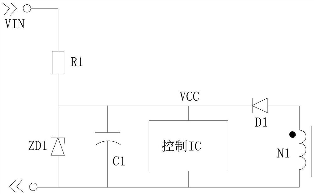
Figure 1 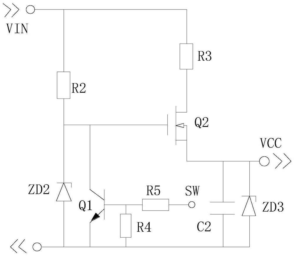
Figure 2 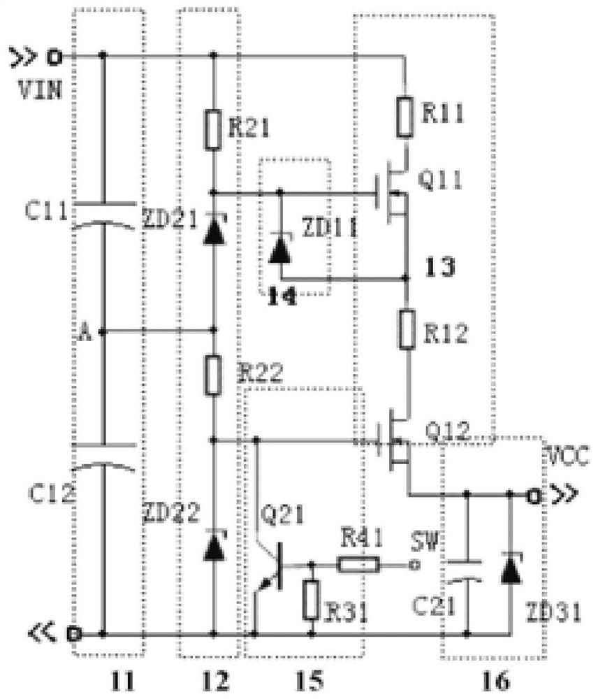
Figure 3
Abstract
Description
technical field
[0001] The invention relates to a power supply module and a switching power supply PWM auxiliary power starting circuit, in particular to a starting circuit of an ultra-wide voltage auxiliary power PWM chip; the input voltage can be as wide as 100-2000V. Background technique
[0002] In photovoltaic inverters and ultra-high voltage direct current transmission systems, the voltage range is very wide, as low as 100 volts and as high as more than 4,000 volts, so it is difficult to design the auxiliary power supply of the system, especially the design of the high-voltage shoulder circuit Difficulties. On the one hand, it is necessary to find electronic components that can withstand high voltage. On the other hand, in terms of reliability, it is necessary to reduce the circuit loss of the shoulder part to prevent heat damage to key components.
[0003] Currently commonly used switching power supply startup circuits (such as figure 1 As shown), since the resistor ...
Examples
Embodiment 1
[0047] see Figure 5 , a starting circuit for an ultra-wide voltage auxiliary power supply PWM chip, comprising a voltage switch circuit 1, a voltage detection circuit 2 and a charging circuit 3; the voltage switch circuit 1 is composed of a MOS transistor Q1, a resistor R4 and a resistor R5; the voltage detection circuit 2 is composed of MOS transistor Q2, resistor R7 and resistor R8; charging circuit 3 is composed of resistor R1 and resistor R2; the drain of MOS transistor Q1 is connected to one end of resistor R1 and resistor R2, and the other end of resistor R1 is connected to the voltage input interface +Vin terminal, the other end of resistor R2 is connected to the source of MOS transistor Q1 and the source of MOS transistor Q2, the gate of MOS transistor Q1 is connected to the drain of MOS transistor Q2; the gate of MOS transistor Q1 is connected to the drain of MOS transistor Q2 Connect the drain connection line of the resistor R4 to the voltage input interface +Vin te...
Embodiment 2
[0062] see Image 6 , is a schematic diagram of a two-stage voltage divider series circuit. When it is applied to 100-1000VDC, the advantages are obvious; the description is as follows. When the minimum input voltage is 100VDC, the charging current is set to: 50uA, and the charging resistance is: R1=R2 =R3=100VDC / 50uA=2MΩ, the same as the above analysis, when the input voltage is applied, the charging current is only: I=Vinmax / (R1+R2+R3)=1000VDC / 6MΩ=166mA, the current change is only 1:3. The power loss is: P=I*Vinmax=166mW. Image 6 The voltage of MOS tube Q1 and MOS tube Q3 in the circuit should be: V Q1 =V Q3 =1 / 3Vinmax=330VDC.
[0063] Figure 1-Figure 4 , then the charging current is 50-500uA, the current changes very large, nearly 1:10, and the power loss is P=I*Vinmax=500mW.
[0064] figure 2 The voltage in the MOS transistor Q2 should be V Q2 =Vinmax=1000VDC, image 3 Q11, Q12 in the V Q11 =V Q12 =1 / 2Vinmax=500VDC.
Embodiment 3
[0066] see Figure 7 , which is a schematic diagram of a three-stage voltage divider series circuit. When it is applied to 100-2000VDC, the advantages are more prominent; as explained below, when the minimum input voltage is 100VDC, the charging current is set to 50uA, and the charging resistance is: R1=R2 =R3=R41=100VDC / 50uA=2MΩ, the same as the above analysis, when the input voltage is applied, the charging current is only: I=Vinmax / (R1+R2+R3+R41)=1000VDC / 8MΩ=125uA, the current change is only 1:2.5. The power loss is: P=I*Vinmax=250mW. Figure 7 The voltage of Q1, Q3, Q5 in should be: V Q1 =V Q3 =V Q5 =1 / 4Vinmax=500VDC.
[0067] Figure 1-Figure 4, then the charging current is 50-1000uA, the current changes very large, nearly 1:20, and the power loss is P=I*Vinmax=2000mW.
[0068] figure 2 The voltage in the MOS transistor Q2 is V Q2 =Vinmax=2000VDC, image 3 , Figure 4 MOS tube Q11, MOS tube Q12, Qa, Qb in the V Q11 =V Q12 =1 / 2Vinmax=1000VDC.
[0069] In the...