
Pneumatic circuit for numerically controlled lathe pneumatic door opening and closing
A technology of CNC lathes and pneumatic circuits, which is applied to metal processing machinery parts, maintenance and safety accessories, metal processing equipment, etc. Deformation of the guide rail of the pneumatic door, meeting the door opening and closing time requirements, and the effect of closing the door with small vibration and impact
Patent Information
- Authority / Receiving Office
- CN · China
- Current Assignee / Owner
- Publication Date
- 2018-04-20
Smart Images
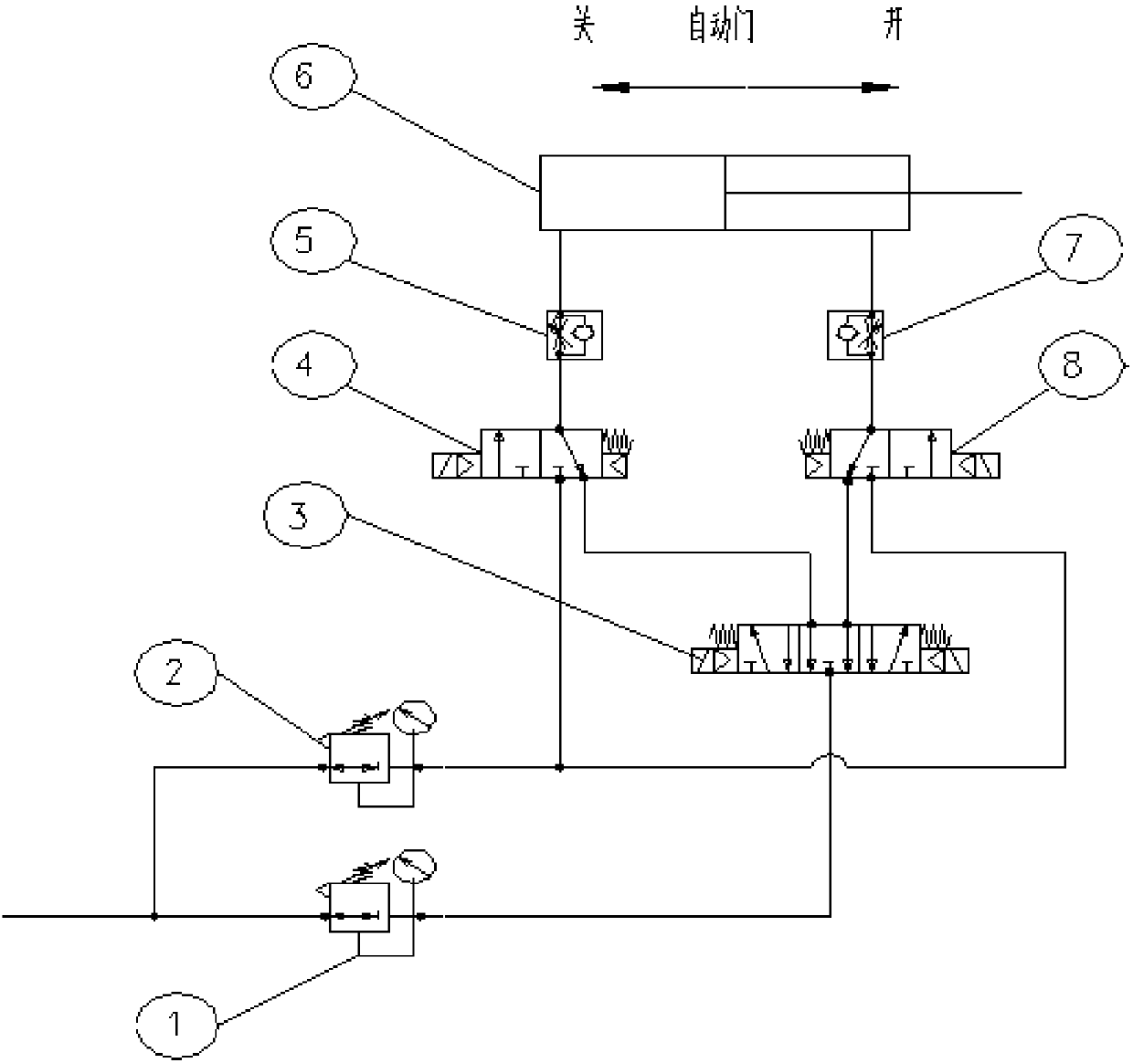
Figure 1
Abstract
Description
technical field
[0001] The invention relates to the technical field of control equipment for a pneumatic door of a numerical control machine tool, in particular to a pneumatic circuit for a pneumatic door switch of a numerical control lathe. Background technique
[0002] Due to the special structural requirements, the pneumatic door of CNC wheel hub car used in the prior art has a structural mass that is too large, for example, the mass will be greater than 200kg. At the same time, the customer requires the opening and closing time of the pneumatic door to be as short as possible, and some technical requirements need to be met within 5S. The inner and pneumatic doors can reach a reciprocating stroke of 900mm, minimizing the auxiliary working time of the equipment. The impact of the short switching time of the pneumatic door and the reduction of the auxiliary working time of the equipment is that the faster running speed causes large vibration, large inertia, and poor cushion...
Examples
Embodiment Construction
[0011] In order to better understand the present invention, the implementation manner of the present invention will be explained in detail below in conjunction with the accompanying drawings.
[0012] combine figure 1 , a pneumatic circuit for a pneumatic door switch of a CNC lathe, comprising an exhaust circuit, the exhaust circuit is provided with a high-speed, high-load pneumatic buffer circuit, and the high-speed, high-load pneumatic buffer circuit includes a single-rod double-acting cylinder 6, Pressure reducing valve one 1, pressure reducing valve two 2, speed regulating valve one 5, speed regulating valve two 7, solenoid valve one 4, solenoid valve two 8, solenoid valve three 3, the gas source passes through the pipeline and the pressure reducing valve on the pipeline Pressure valve 1 is connected to the air port on the air source connection side of solenoid valve 3 3, one air port on the cylinder connection side of solenoid valve 3 3 is connected to the air port on the...