
Mop forming machine
A molding machine and mop technology, applied in cleaning machinery, carpet cleaning, floor cleaning, etc., can solve the problems of high structural failure rate, surface wear of mop rod, large outward centrifugal force of the claw grasping device, etc., and achieve stable operation structure. , The effect of stable structure and convenient operation
Patent Information
- Authority / Receiving Office
- CN · China
- Current Assignee / Owner
- Publication Date
- 2021-04-30
Smart Images
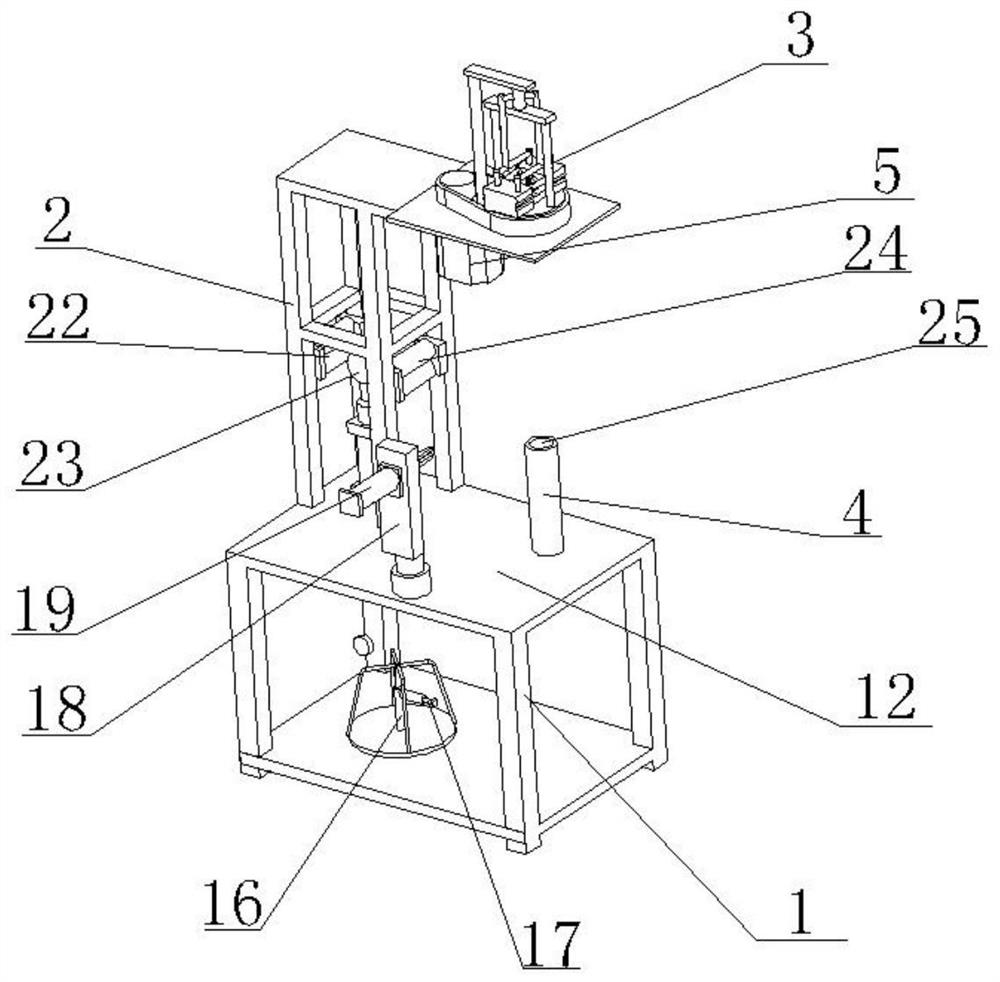
Figure 1 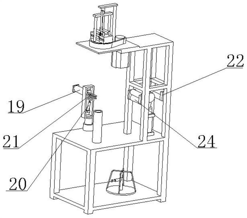
Figure 2 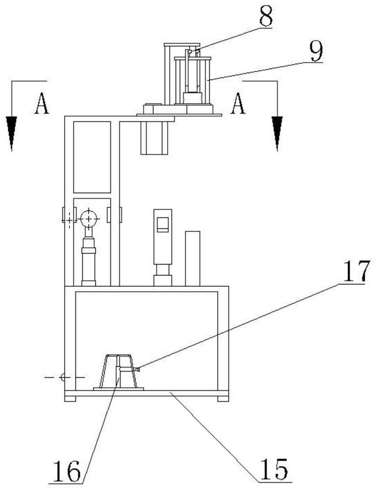
Figure 3
Abstract
Description
technical field
[0001] The invention relates to the field of textile machinery, in particular to a mop forming machine. Background technique
[0002] The operation mode of the traditional mop forming machine is as follows: firstly, the lower end of the mop rod is fixed by a claw grabbing device similar to a three-catch chuck, and then the whole mop rod is driven to rotate, and finally the cleaning thread is fixed on the lower part of the mop rod by winding wires. Form a mop head. There are following problems in this kind of structure: 1. The claw grabbing device grabs and fixes the lower end of the mop rod through a plurality of claws, so the claws are inevitably subjected to the torque force generated when the mop rod rotates, and the mop rod Due to its own gravity and the outward centrifugal force generated by the rotation of the mop rod, it is often prone to breakage and damage, and the structural failure rate is high. 2. The structure of the claw grabbing device is pre...
Examples
Embodiment
[0028] Embodiment: A mop forming machine, including a base 1, an upper bracket 2, a clamping rotation unit, an outlet unit, a power output unit, and a control center respectively connecting the clamping rotation unit, the outlet unit, and the power output unit. An operating platform 12 is provided on the upper surface of the base 1 , and the upper bracket 2 is fixedly installed on the operating platform 12 . The clamping rotation unit includes a clamping rotation device 3 and a limit support device 4 , and the clamping rotation device 3 is installed on the upper end of the upper bracket 2 . The clamping hole 7 corresponding to the limit support device 4 is provided at the lower end of the clamping and rotating device 3 , and the clamping and rotating device 3 can clamp and rotate the mop rod.
[0029] The clamping and rotating device 3 includes a driving motor 5, a movable turntable 6, a clamping assembly, a rotary joint 8, and a rotating bracket 9. The driving motor 5 and the...