
Bearingless permanent magnet speed regulation system
A permanent magnet speed regulation and bearingless technology, which is applied in the direction of permanent magnet clutch/brake, casing/cover/support, control of mechanical energy, etc., can solve the problem of high maintenance cost of permanent magnet speed governor, large amount of renovation work, Long time and other problems, to achieve the effect of being suitable for popularization, reducing the amount and cost of renovation projects, and low cost
Patent Information
- Authority / Receiving Office
- CN · China
- Patent Type
- Applications(China)
- Current Assignee / Owner
- Publication Date
- 2021-08-10
Smart Images
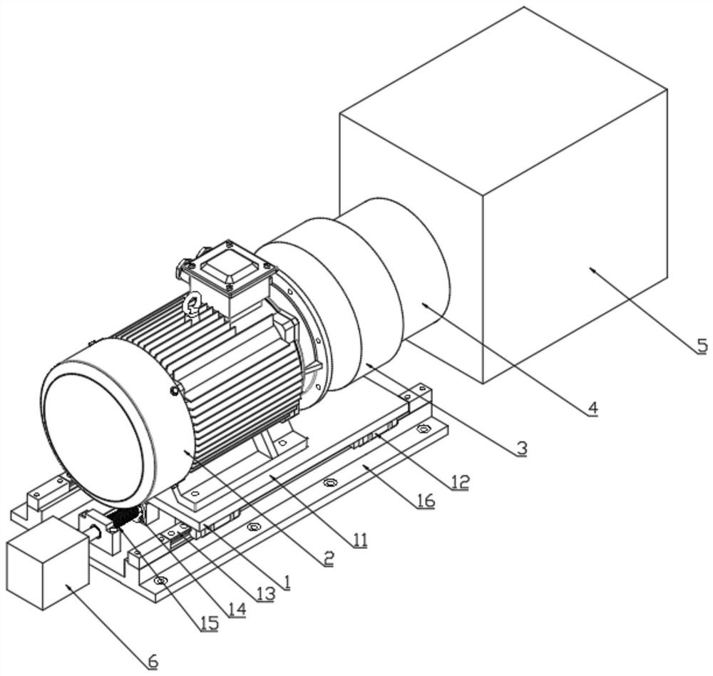
Figure 1 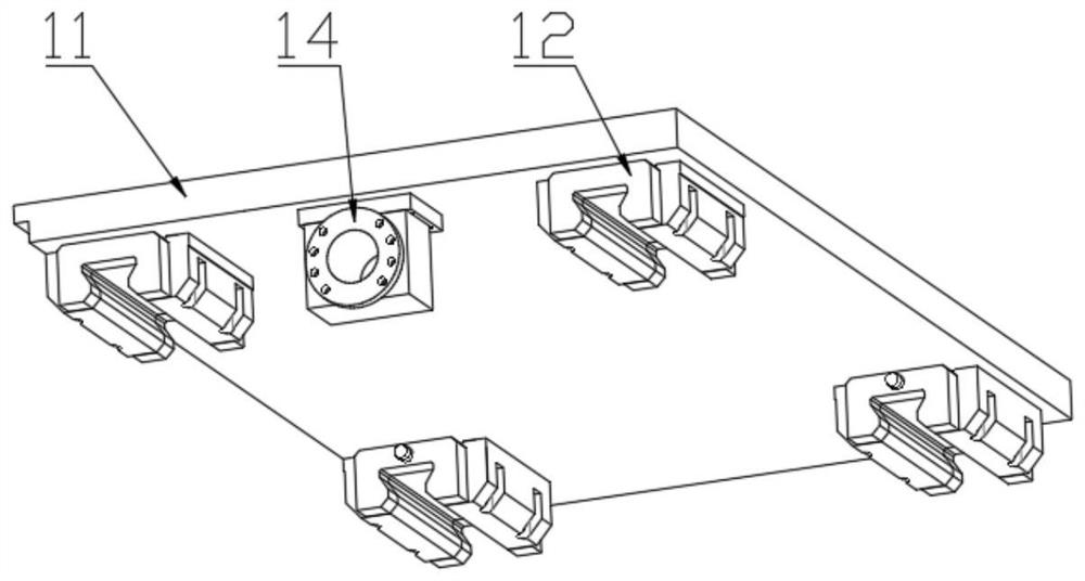
Figure 2 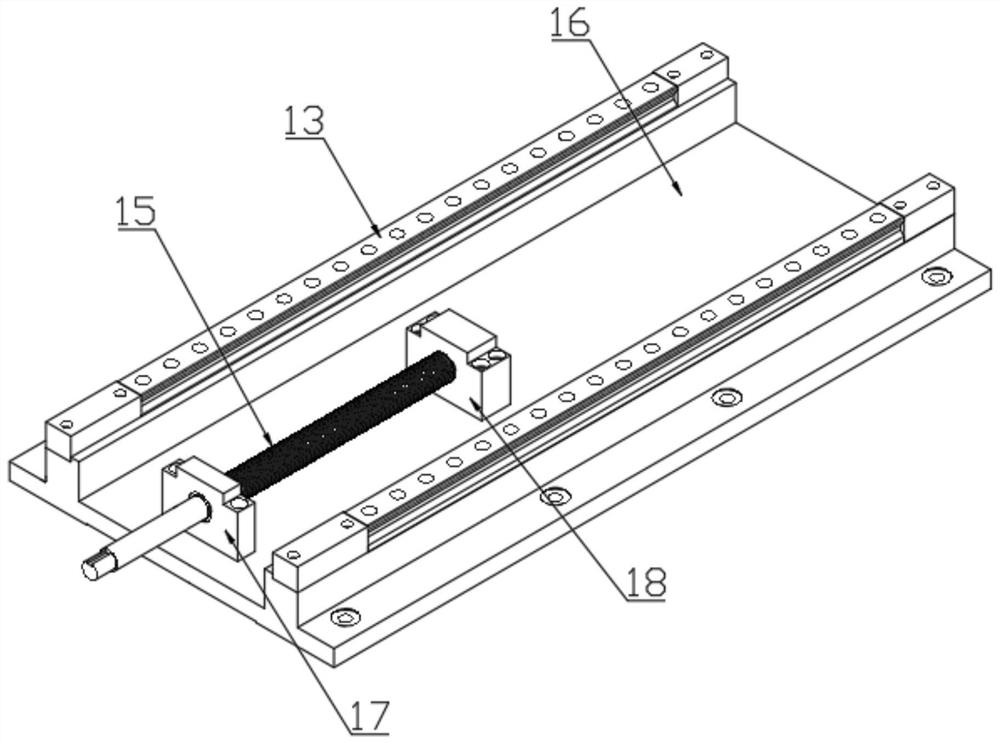
Figure 3
Abstract
Description
technical field
[0001] The invention relates to the technical field of permanent magnet speed regulation, in particular to a bearingless permanent magnet speed regulation system. Background technique
[0002] The permanent magnet governor is a device that uses magnetic force to achieve power transmission and speed regulation. It has the characteristics of simple structure, high reliability, and strong environmental adaptability. The permanent magnet governor adjusts the magnetic field coupling area between the conductor rotor and the permanent magnet rotor through the adjustment mechanism, thereby changing the transmitted torque and speed. At present, there are two main problems in the use of permanent magnet governors. One is that the permanent magnet governor contains bearings, which need to be maintained and replaced regularly, which increases the cost of the permanent magnet governor. The second is the permanent magnet governor. The inverter requires installation space....
Examples
Embodiment Construction
[0017] The present invention will be further described below in conjunction with the accompanying drawings and embodiments.
[0018] Such as Figure 1 to Figure 3 As shown, a bearingless permanent magnet speed regulating system includes a mobile base (1), a motor (2), a cylindrical conductor rotor (3) and a cylindrical permanent magnet rotor (4).
[0019] The mobile base (1) also includes an upper base plate (11), a slide block (12), a guide rail (13), a leading screw nut (14), a leading screw (15), and a lower base plate (16). The slide block (12) and the lead screw nut (14) are arranged on the lower end surface of the upper bottom plate (11), and the motor (2) is arranged on the upper end surface of the upper bottom plate (11). Guide rails (13) and leading screw (15) are arranged on the upper end surface of lower bottom plate (16), and guide rails (13) are no less than 2 pieces. The mobile base (1) also includes a support seat A (17) and a support seat B (18), and the supp...