
Bevel tooth differential speed reducer for mechanical main shaft of machine tool
A reducer and mechanical technology, which is applied in the direction of mechanical equipment, differential transmission, belt/chain/gear, etc., can solve the control requirements of increasing or reducing the output power and output torque of the reducer, and the output torque of the motor reducer. Torque drop, unable to meet the rated output torque and other problems
Patent Information
- Authority / Receiving Office
- CN · China
- Current Assignee / Owner
- Publication Date
- 2022-03-04
- Estimated Expiration
- Not applicable · inactive patent
Smart Images
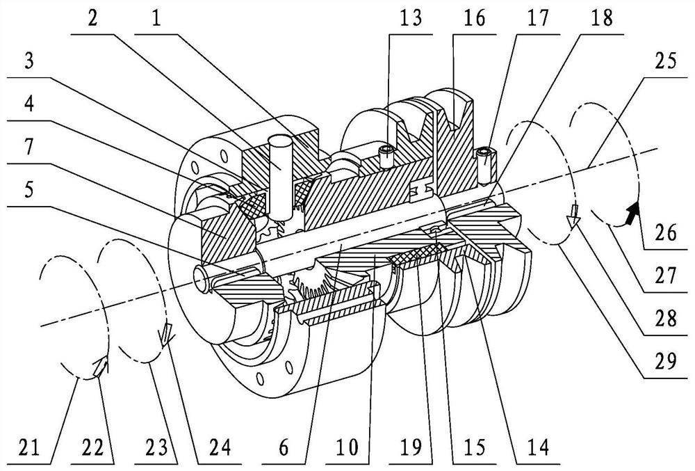
Figure 1 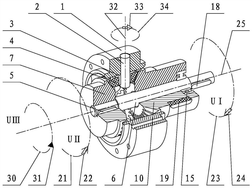
Figure 2 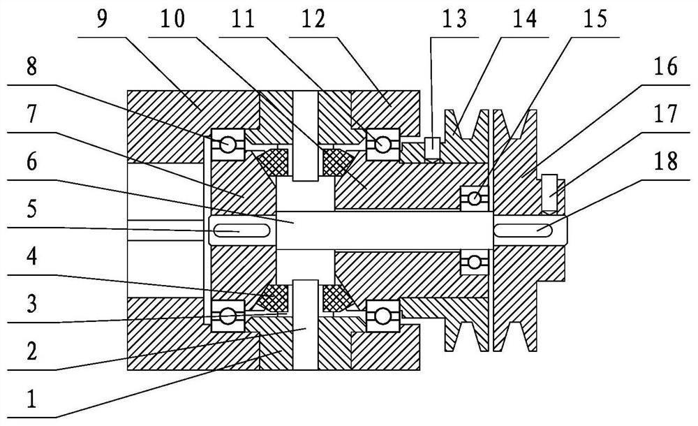
Figure 3
Abstract
Description
technical field
[0001] The invention relates to a bevel gear differential speed reducer for a machine tool mechanical spindle, which relates to a reducer, in particular to a planetary support and an output flange located radially outside of bevel gear 1 and bevel gear 2, with a large rated output torque The machine tool mechanical spindle bevel gear differential reducer. Background technique
[0002] The double bevel gear differential speed reduction mechanism of application publication number CN109854681A is a double bevel gear differential speed reduction mechanism that adopts two motors to respectively drive the speed difference between the first double bevel gear and the second double bevel gear to obtain a low speed output. Application publication number CN109736047A relates to a method for controlling a double bevel gear differential speed reduction system of a washing machine, which is a method in which a double bevel gear differential speed reduction mechanism is app...
Examples
Embodiment Construction
[0048] The present invention is further described below in conjunction with accompanying drawing.
[0049] refer to Figure 1 to Figure 4 , the reducer includes an output flange part, a planet carrier part, a pressure sleeve part, and a linkage shaft part. The output flange components include an output flange 9, a bevel gear II 7 and a bearing II 8. The planet carrier components include a planet carrier 1 , a planet shaft 2 , a planet sleeve 3 and a planet bevel gear 4 . Press sleeve parts comprise press sleeve 12, bevel gear one 10, bearing one 11, bearing three 15, pulley one 14, set screw one 13, key bar three 19, set screw 20. The linkage shaft parts include linkage shaft 6, key bar one 18, key bar two 5, belt pulley two 16, set screw two 17. The output flange parts, planetary support parts, and pressure sleeve parts are arranged in sequence along the axial direction, and the output flange parts, planetary support parts, and pressure sleeve parts are connected and fixed...