
Cyclic preheater for single cavity permanent-magnet rotor pump and assembly method thereof
A permanent magnet rotor and pump circulation technology, applied in the direction of machine/engine, engine components, engine starting, etc., can solve problems such as unreasonable overall structure, achieve the effect of reducing the number of parts, reducing manufacturing costs, and simple molds
Patent Information
- Authority / Receiving Office
- CN · China
- Patent Type
- Applications(China)
- Current Assignee / Owner
- Publication Date
- 2005-09-07
- Estimated Expiration
- Not applicable · inactive patent
Smart Images
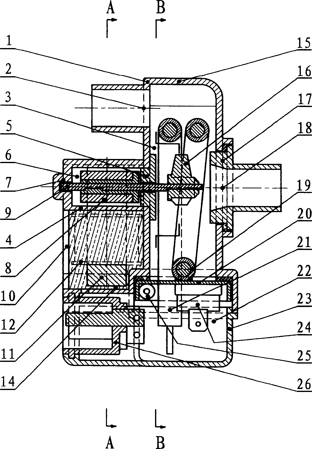
Figure 1 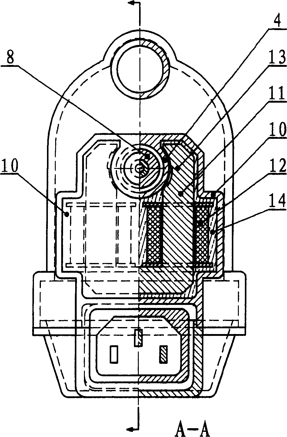
Figure 2 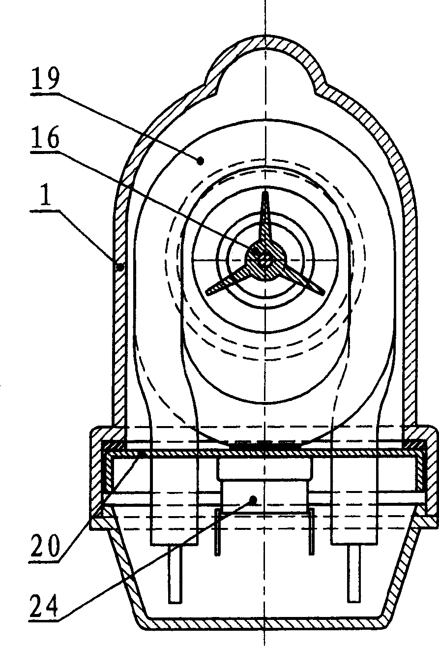
Figure 3
Abstract
Description
technical field
[0001] The invention relates to a single-cavity permanent magnet rotor pump circulation preheater and its assembly method, which belongs to the field of motor vehicle engine electric preheaters, and can also be applied to preheating, heating, temperature control, etc. of other engines and other machinery and equipment field. Background technique
[0002] In a low temperature environment, motor vehicle engines will have difficulty starting due to fuel condensation, oil viscosity and other reasons. The most ideal way to solve this problem is to heat the engine in advance, this process is generally called warm-up. Through preheating, the cold start becomes a hot start, which not only starts smoothly, but also greatly reduces engine wear, and can also greatly reduce the emission of polluting gases in the engine exhaust and reduce fuel consumption.
[0003] In order to achieve preheating, a preheater is usually installed on the engine. Compared with other prehe...
Examples
Embodiment Construction
[0027] The specific implementation and examples of the present invention will be described below in conjunction with the accompanying drawings.
[0028] Depend on figure 1 , figure 2 , image 3 It can be seen that the main structure of the device of the present invention is a closed chamber, which communicates with the outside only through the inlet (18) and outlet (2) on it, and the chamber is divided into a smaller rotor chamber (6) and a larger heating chamber (3) Two parts, the two parts communicate through the rotor cavity, and the positional relationship between them is that the rotor cavity is on a side wall of the heating cavity (3), and the rotor cavity (6) protrudes outward from the rotor cavity Outside the heating chamber (3). Such a positional relationship shows that the rotor cavity opening is the interface between the rotor cavity (6) and the heating cavity (3). After the front bearing (5) is installed on the rotor cavity opening, the front bearing (5) connec...