
Disposable centrifugal blood pump with magnetic coupling
a centrifugal blood pump and magnetic coupling technology, which is applied in the direction of pumps, positive displacement liquid engines, fluid engines, etc., can solve the problems of durability, plaque formation around bearings or hemolysis, and limited expiration dates for use of disposable parts, so as to reduce the cost of disposable parts and reduce the magnetic resistance of the magnetic circuit. , the effect of simple rotor structur
Patent Information
- Authority / Receiving Office
- US · United States
- Patent Type
- Applications(United States)
- Current Assignee / Owner
- Publication Date
- 2010-02-18
Smart Images
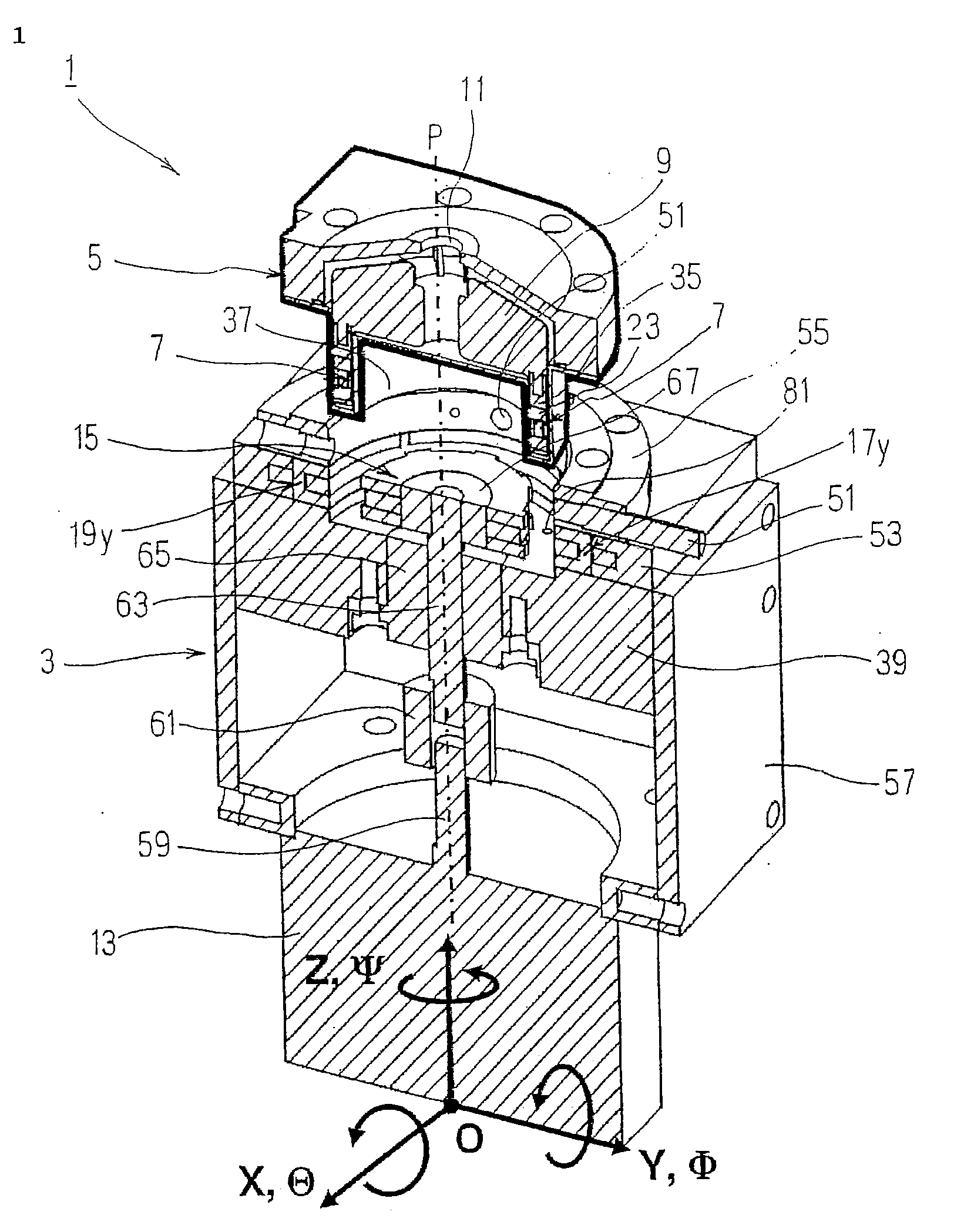
Figure 1 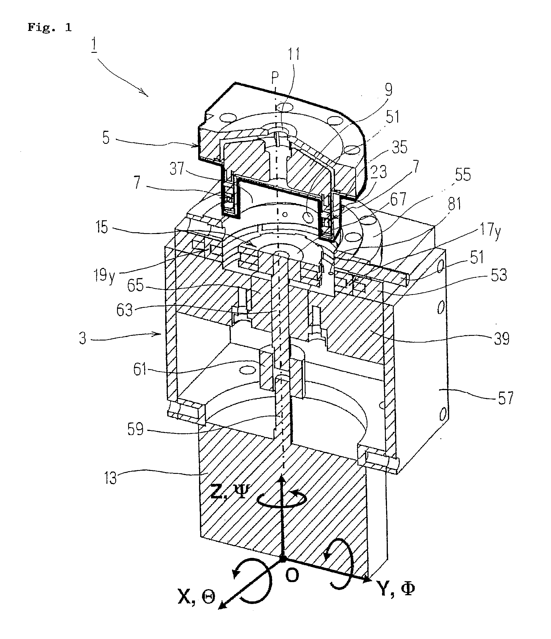
Figure 2 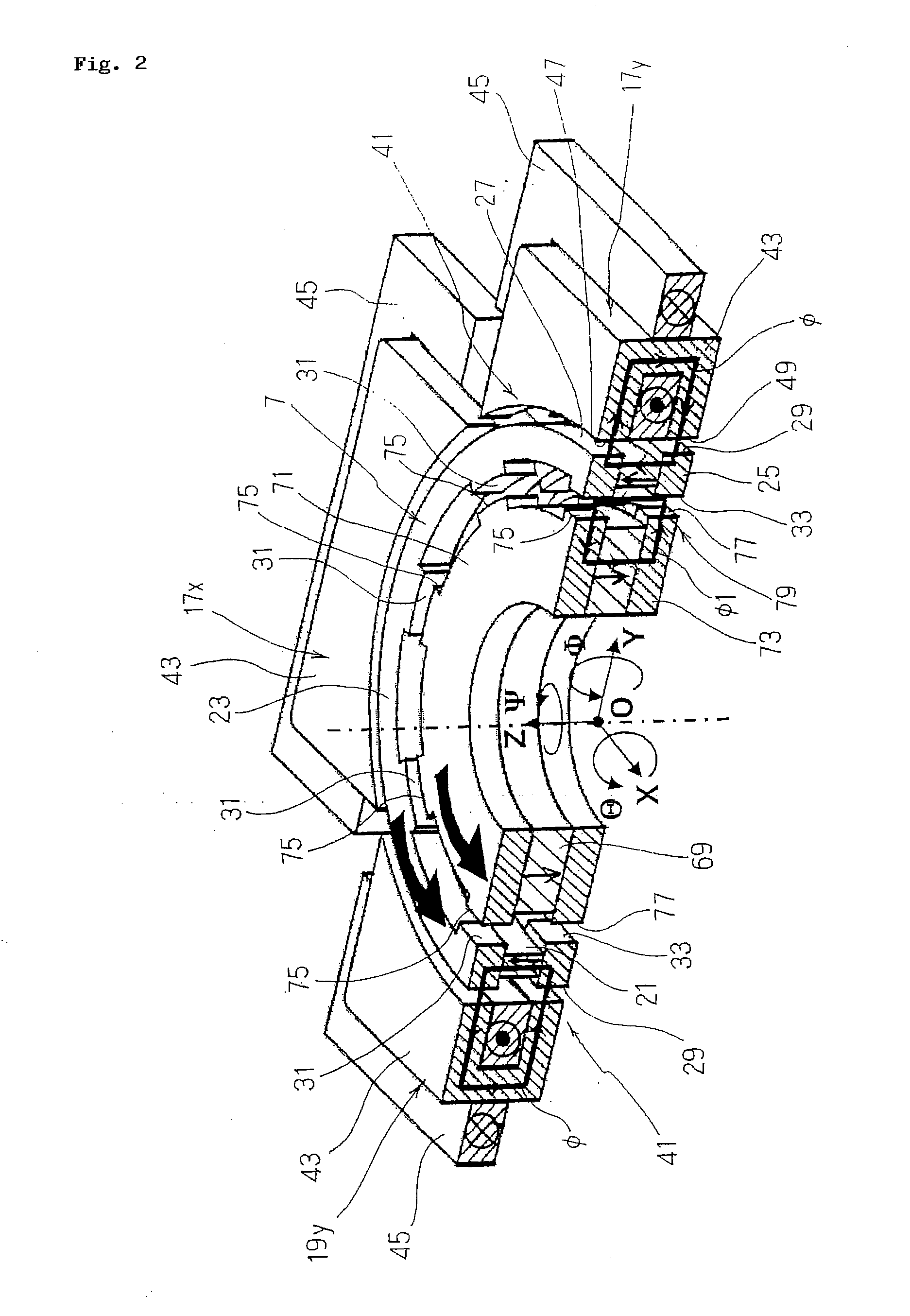
Figure 3
Abstract
Description
TECHNICAL FIELD
[0001] The present invention relates to a centrifugal blood pump in which only blood-contact parts are disposable parts and, more specifically, to a disposable centrifugal blood pump with magnetic coupling employing a magnetic coupling rotor which is simple in structure of the disposable parts, has a small number of permanent magnets, is low cost, and is easy to manufacture.BACKGROUND ART
[0002] In the related art, as a centrifugal blood pump used during cardiac surgery or after cardiac surgery, a disposable centrifugal blood pump in which only an impeller (vane wheel) which comes into contact with blood of a patient and a housing (pump housing) for storing the same are replaced is used.
[0003] Normally, in the disposable centrifugal blood pump of this type, the impeller is supported by a pivot bearing or a contact bearing protected by a mechanical seal. However, since the bearing is used without lubrication in order to avoid contamination of blood, it is subjected to inte...
Examples
first embodiment
[0031]FIG. 1 to FIG. 6 illustrate a disposable centrifugal blood pump with magnetic coupling (hereinafter referred to as “centrifugal blood pump with magnetic coupling”) according to Claim 1 to Claim 3. As shown in FIG. 1, a centrifugal blood pump with magnetic coupling 1 according to this embodiment includes a stator 3 and a housing5 which is detachably attached to the upper surface of the stator 3 and, as described below, a blood-contact part including the housing 5, a rotor 7, an impeller 9, and so on mounted to the interior thereof and being surrounded by a thick line in the drawing corresponds to a disposable part, and blood flowed from an inflow 11 on top of the housing 5 is provided with kinetic energy by the rotation of the impeller 9 and flowed out from an outflow (not shown) on a side surface thereof.
[0032]Then, the stator 3 including a brushless DC motor (hereinafter referred to as “motor”) 13 arranged apart from the housing 5, a torque transmission disk 15 rotating synch...
second embodiment
[0101]FIG. 9 shows the centrifugal blood pump with magnetic coupling according to Claim 1 to Claim 3, and in the embodiment shown in FIG. 1 to FIG. 6, the four electromagnets 17x, 19x, 17y, 19y are arranged around the rotor 7 (housing 5) at the intervals of 90°. However, three electromagnets 109, 111, 113 having the same structure as the electromagnet 17y may be arranged around the rotor 7 (housing 5) at regular intervals of 120° as shown in FIG. 9.
[0102]According to this embodiment, there are infinite numbers of combination as methods of power supply to the coils 45 of the respective electromagnets 109, 111, 113. As an example, by providing an electric current ix to the electromagnet 109 and providing an electric current -ix in the opposite direction to the electromagnet 111, a drive force only in the direction X is generated.
[0103]The configuration of other parts is the same as the embodiment shown in FIG. 1, and hence description thereof will be omitted.
[0104]In this manner, acco...