
Image forming apparatus
Patent Information
- Authority / Receiving Office
- US · United States
- Current Assignee / Owner
- Publication Date
- 2010-12-02
Smart Images
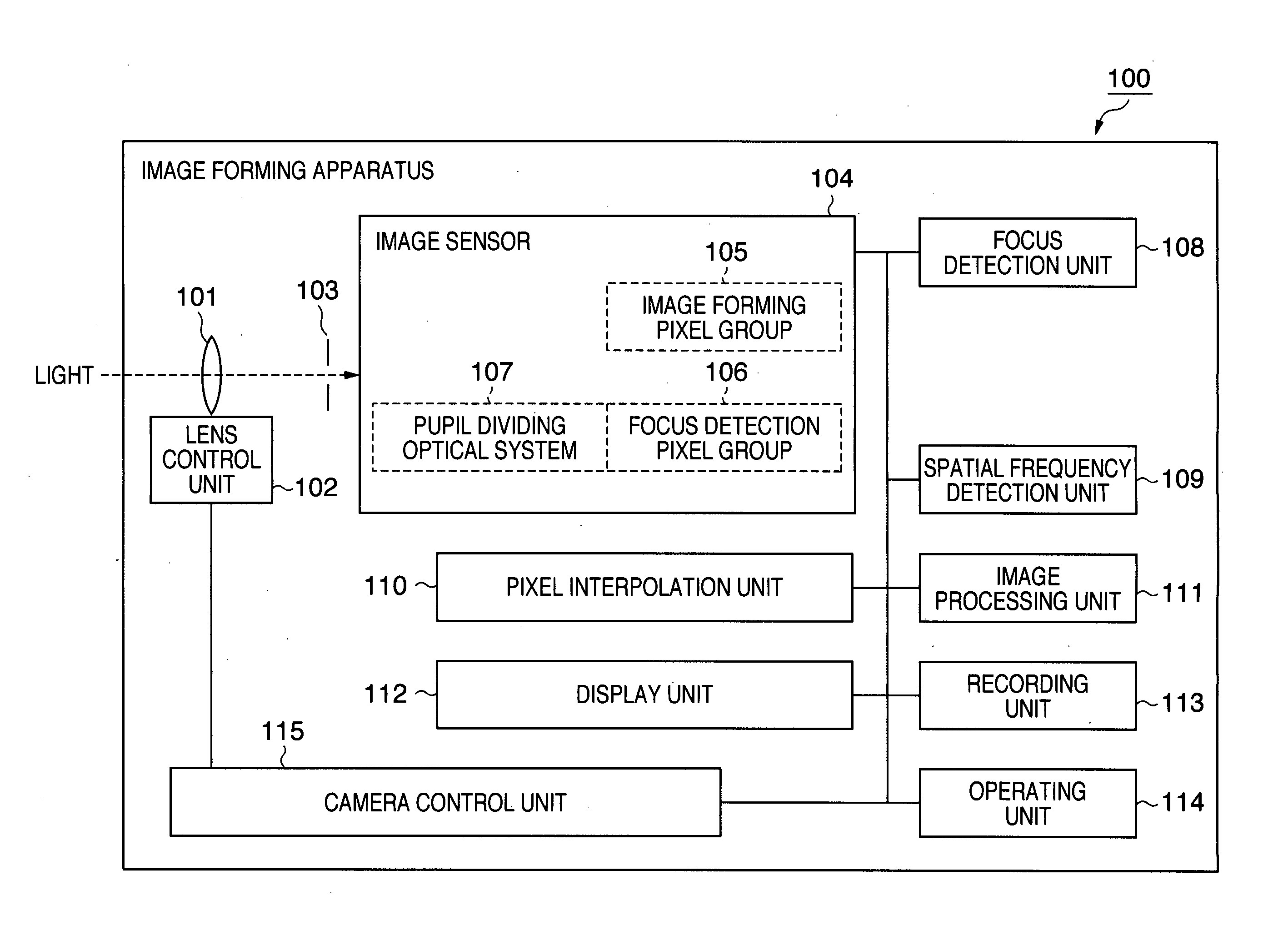
Figure 1 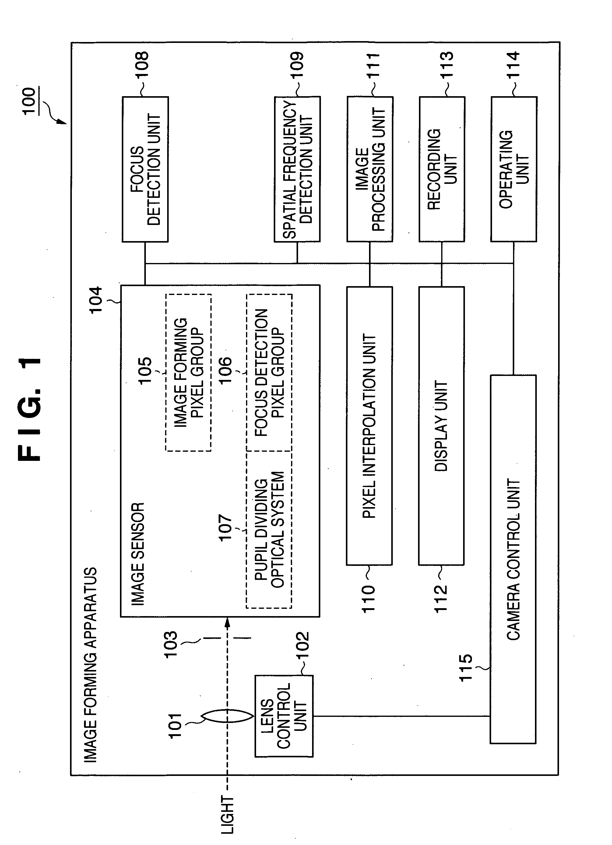
Figure 2 
Figure 3
Abstract
Description
TECHNICAL FIELD
[0001] The present invention relates to an image forming apparatus for forming an image of a subject, and more particularly, to an image forming apparatus for focusing based on output signals from an image sensor.BACKGROUND ART
[0002] In recent years, compact digital cameras and single-lens reflex digital cameras have become mainstream, instead of cameras using silver-halide films.
[0003] In the silver-halide film age, phase difference autofocus was carried out by a triangulation method, with a sensor dedicated to autofocus (hereinafter referred to as AF) provided in order to carry out focusing automatically.
[0004] However, with digitalization, some compact digital cameras carry out contrast autofocus, in which the focus lens position leading to the sharpest image is searched for while driving the focus lens in the same way as video cameras. This allows cost reduction due to elimination of a conventional sensor dedicated to AF, resolution of parallax with an optical viewfin...
Examples
first embodiment
[0042]FIG. 1 is a block diagram illustrating an example of the entire configuration of an image forming apparatus according to a first preferred embodiment of the present invention.
[0043]In FIG. 1, an image forming apparatus 100 includes a lens 101 as an image forming optical system for forming an image of a subject, a lens control unit 102 for controlling the focal position of the lens 101, and an aperture 103 for adjusting the amount of incident light. Further, the image forming apparatus 100 includes an image sensor 104 composed of, for example, a CMOS sensor or a CCD.
[0044]The image sensor 104 includes an image forming pixel group 105 composed of pixels for use in acquisition of image signals for forming images (hereinafter referred to as “image forming pixels”), with respective color filters of RGB provided on their light-receiving planes. Further, the image sensor 104 includes multiple focus detection pixel groups 106 in which multiple sets of pairs of pixels (hereinafter refe...
second embodiment
[0069]FIG. 7 is a flowchart representing focusing operation in an image forming apparatus according to a second preferred embodiment of the present invention. It is to be noted that the image forming apparatus has the configuration shown in FIG. 1 and an image sensor 104 has the pixel arrangement shown in FIG. 5 in the second embodiment. The second embodiment keeps from obtaining a wrong defocus amount due to a sampling error in the case of a subject with a spatial frequency higher than the period of focus detection pixels S1 and S2 arranged dispersedly.
[0070]In step S91, signals are read out from the focus detection pixels S1 and S2. In step S92, the signals read out in step S91 are subjected to correlation calculation, and in step S93, a focus lens contained in a lens 101 is driven. Next, in step S94, image signals are read out from image forming pixels around the focus detection pixels S1 and S2 which have output the signals used for the correlation calculation. In step S95, it i...
third embodiment
[0082]FIG. 9 is a flowchart representing focusing operation in an image forming apparatus according to a third preferred embodiment of the present invention. It is to be noted that, in this third embodiment, the image forming apparatus has the configuration shown in FIG. 1 and an image sensor 104 has the pixel arrangement shown in FIG. 2 or 5.
[0083]In the examples described in the first embodiment and its modification, the focusing area for use in focus detection processing is changed in a case in which a particular pattern, such as a periodical pattern and a fine line, is detected. By contrast, in the processing shown in FIG. 9, when a fine line is detected in step S62, contrast autofocus is carried out in step S163, instead of phase difference autofocus carried out with the use of the focus detection pixels. In the contrast autofocus, the position of the focus lens is controlled to the position with the highest contrast, based on image signals obtained from image forming pixels, w...