
Fluid storage and dispensing system featuring interiorly disposed and exteriorly adjustable regulator for high flow dispensing of gas
a technology of fluid storage and gas, which is applied in the direction of liquid transferring device, container discharge method, transportation and packaging, etc., can solve the problems of inability to monitor the pressure in the storage and dispensing vessel, difficult to determine or predict in advance when the vessel will be empty, and compromised the safety of the fluid storage and dispensing system
Patent Information
- Authority / Receiving Office
- US · United States
- Patent Type
- Patents(United States)
- Current Assignee / Owner
- Publication Date
- 2001-07-10
- Estimated Expiration
- Not applicable · inactive patent
Smart Images
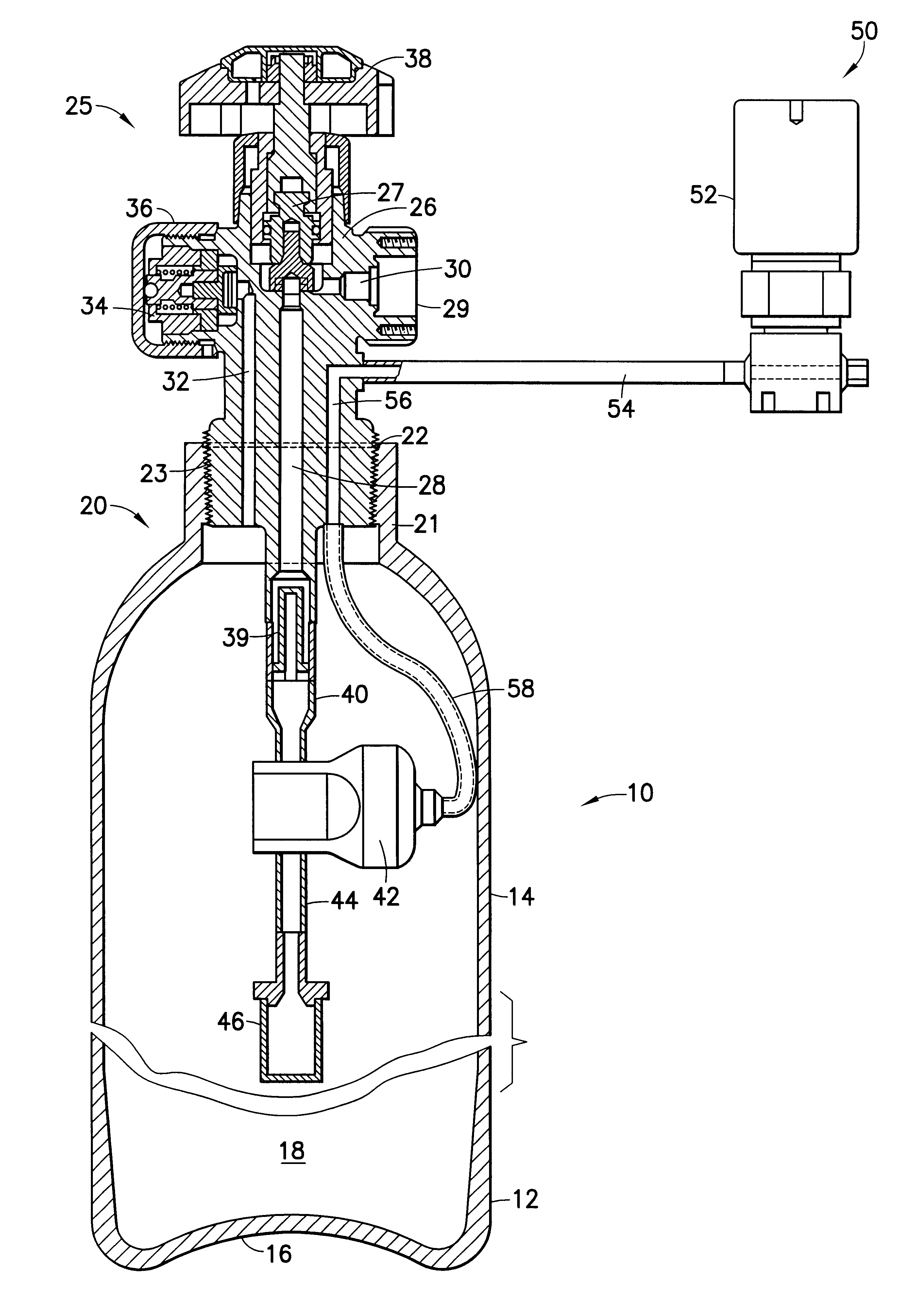
Figure 1 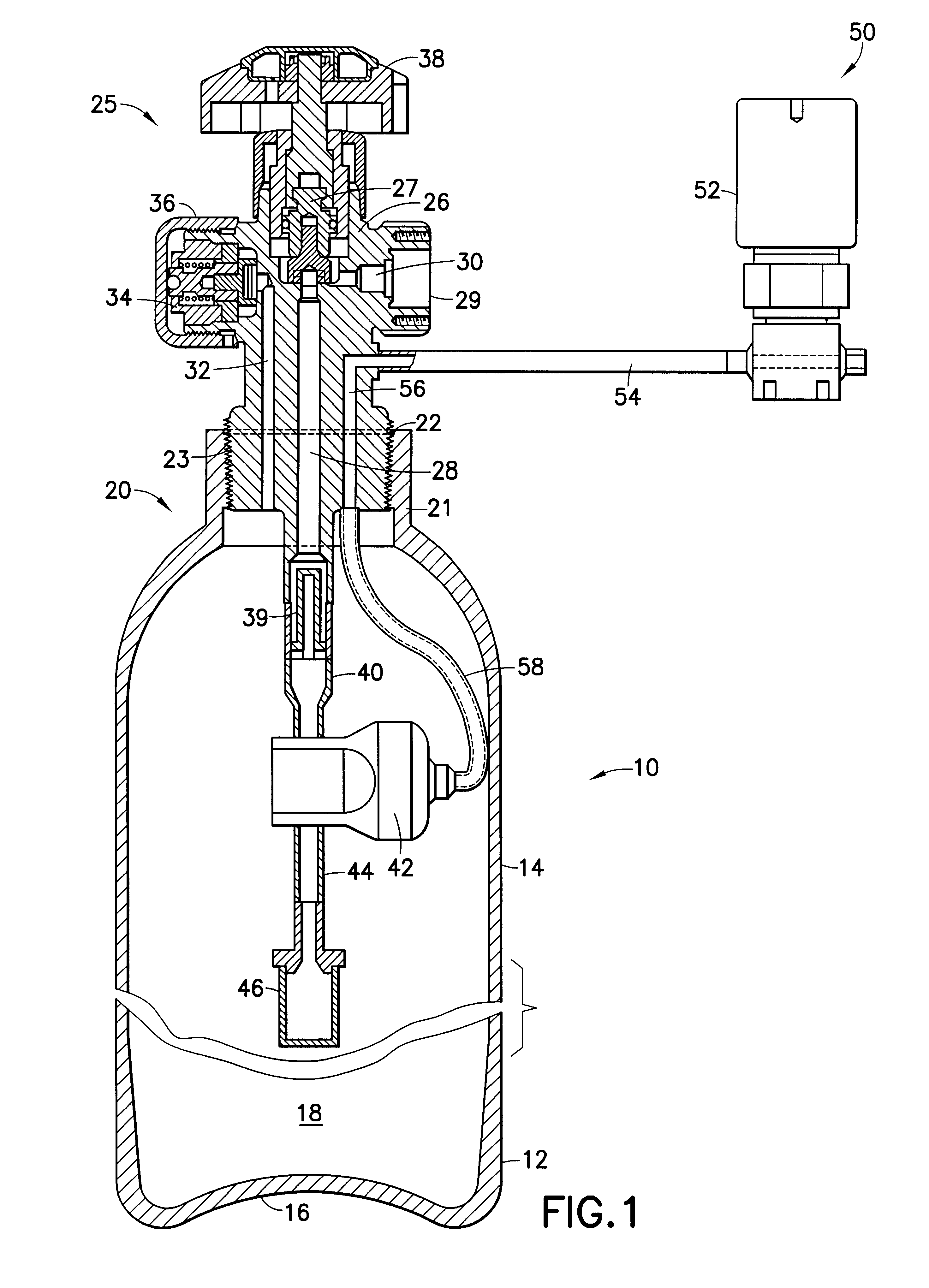
Figure 2 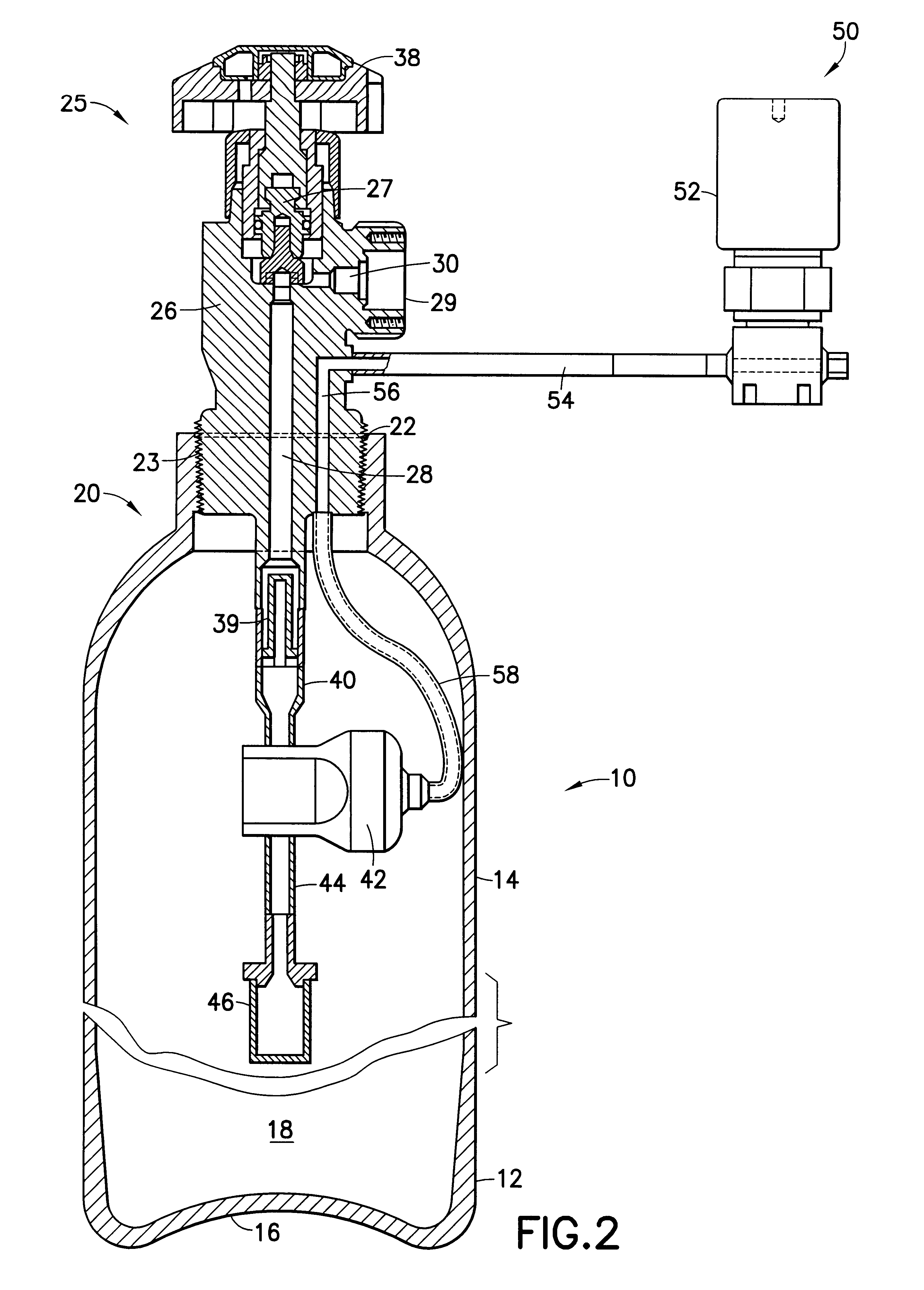
Figure 3
Abstract
Description
1. Field of the InventionThis invention relates to a fluid storage and gas dispensing system that may be utilized to store high pressure liquid or other fluid, for dispensing of gas from the system and use of the dispensed gas in an application such as the manufacture of semiconductor devices and materials.2. Description of the Related ArtIn a wide variety of industrial processes and applications, there is a need for a reliable source of process fluid(s).For example, a safe, reliable and efficient fluid supply source is desirable in the field of semiconductor manufacturing, ion implantation, manufacture of flat panel displays, medical intervention and therapy, water treatment, emergency breathing equipment, welding operations, space-based delivery of liquids and gases, etc.U.S. patent application Ser. No. 09 / 067,393 filed Apr. 28, 1998 in the names of Luping Wang and Glenn M. Tom describes a fluid storage and gas dispensing system including a storage and dispensing vessel for holdin...
Examples
third embodiment
FIG. 3 is a schematic cross-sectional elevation view of a fluid storage and dispensing system according to the present invention, featuring another two ported valve body embodiment. In the FIG. 3 drawing, all corresponding elements and features of the FIG. 1 and FIG. 2 embodiments are correspondingly numbered in FIG. 3 for ease of reference.
The FIG. 3 embodiment differs from the two-ported fluid storage and dispensing system shown in FIG. 2 in that the FIG. 3 embodiment has separate dispensing and fill ports 29 and 34, respectively, and the fill passage 32 is joined at the bottom face of valve body 26 to gas flow line 57. The gas flow line 57 at its opposite end from that joined to the valve body 26 is joined to the regulator 42.
By this arrangement, the fill port in the FIG. 3 embodiment may be coupled to a source of fluid (not shown) for initial charging of the vessel. For such charging operation, the adjustable set point regulator 42 may be set at an appropriate pressure set point...
fourth embodiment
FIG. 4 is a schematic cross-sectional elevation view of a fluid storage and dispensing system according to the present invention. The FIG. 4 embodiment features a three-port valve head body 26 having general similarity in structure to the embodiment of FIG. 1. In FIG. 4, all corresponding elements and features are numbered correspondingly to FIG. 1 for ease of reference.
The FIG. 4 embodiment, in contrast to the fluid storage and dispensing system of FIG. 1, features a second regulator 70 disposed below adjustable set point regulator 42, so that regulator 70 is upstream of regulator 42 in the flow path of the fluid being dispensed from vessel 12 (through particle filter 46, regulator 70, regulator 42, extension tube 40, central vertical passage 28, and gas discharge passage 30 of gas discharge port 29).
The regulator 70, in contrast to the adjustable set point regulator 42, is a set pressure regulator that is fixed or set at a specific pressure set point, which governs its dispensing ...
fifth embodiment
FIG. 5 is a schematic cross-sectional elevation view of a fluid storage and dispensing system according to the present invention. The FIG. 5 embodiment features a three-port valve head body 26 having general similarity in structure to the embodiment of FIG. 1. In FIG. 5, all corresponding elements and features are numbered correspondingly to FIG. 1 for ease of reference.
The FIG. 5 embodiment, in contrast to the fluid storage and dispensing system of FIG. 1, features a second regulator 72 disposed below adjustable set point regulator 42, so that regulator 72 is upstream of regulator 42 in the flow path of the fluid being dispensed from vessel 12 (through particle filter 46, regulator 72, regulator 42, extension tube 40, central vertical passage 28, and gas discharge passage 30 of gas discharge port 29).
The FIG. 5 embodiment has separate dispensing and fill ports 29 and 34, respectively, and the fill passage 32 is joined at the bottom face of valve body 26 to gas flow line 74. The gas...