
Method for operating an internal combustion engine
a technology of internal combustion engine and combustion chamber, which is applied in the direction of machines/engines, electric control, instruments, etc., can solve the problems of unfavorable spray preparation and therefore combustion, formation of deposits in the combustion chamber, and low torque of the corresponding cylinder, so as to reduce the nox emission and reduce the combustion temperature. , the effect of simple means
Patent Information
- Authority / Receiving Office
- US · United States
- Patent Type
- Patents(United States)
- Current Assignee / Owner
- Publication Date
- 2005-05-17
- Estimated Expiration
- Not applicable · inactive patent
Smart Images
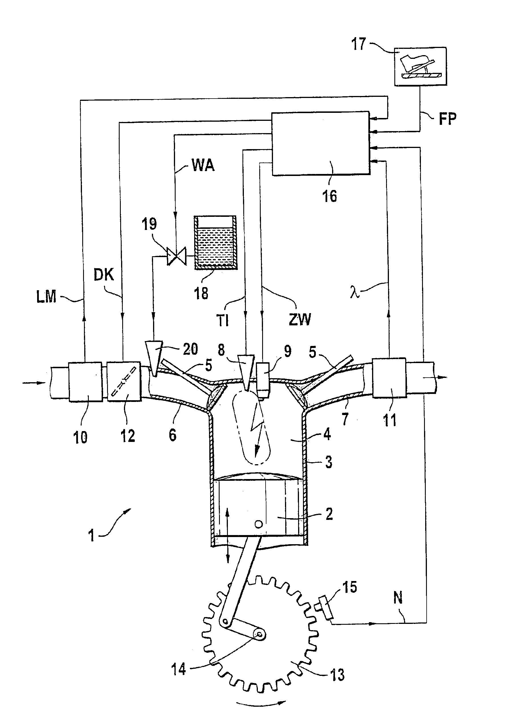
Figure 1 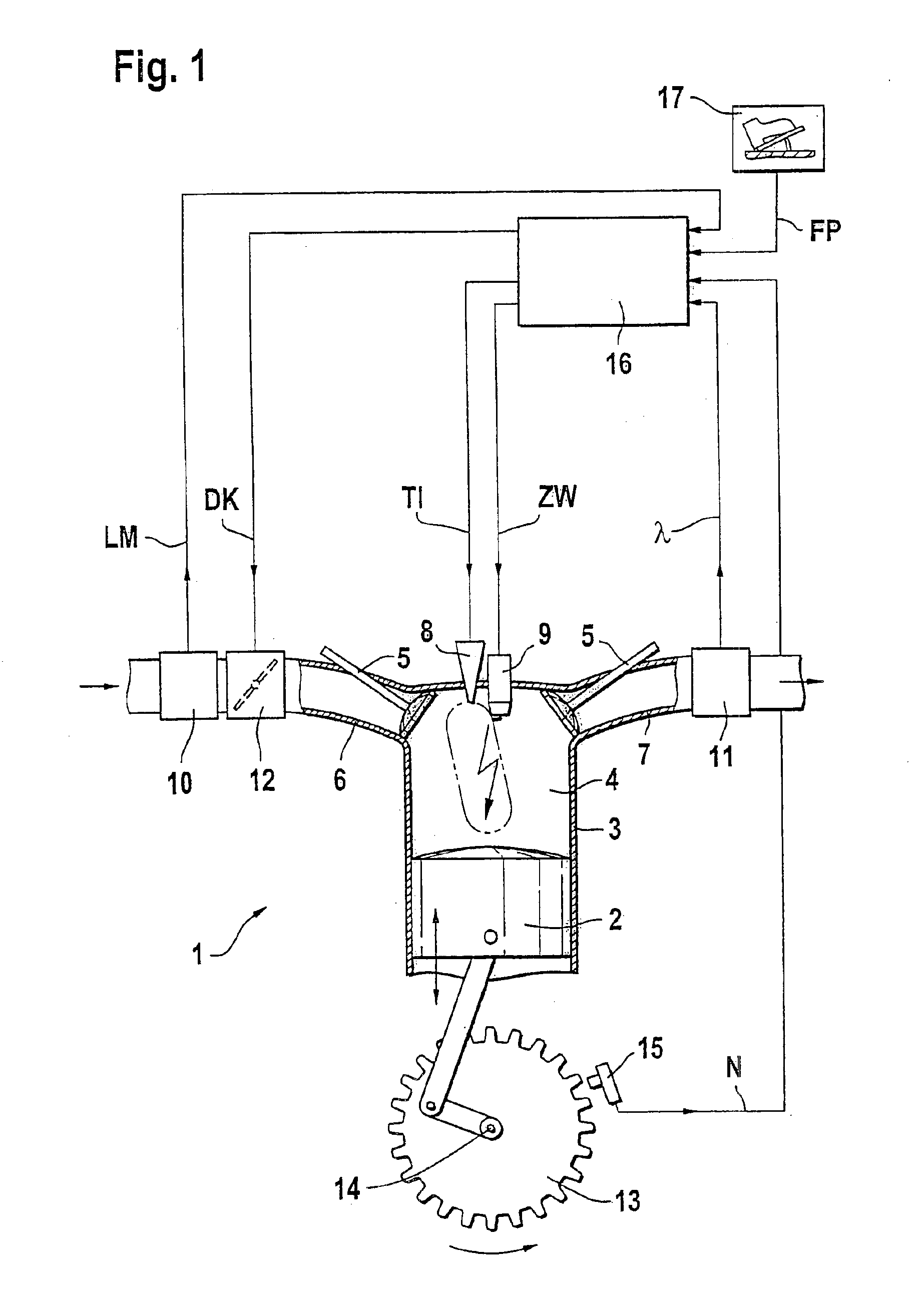
Figure 2 
Figure 3
Abstract
Description
FIELD OF THE INVENTION
[0001] The invention relates to a method and an arrangement for operating an internal combustion engine, especially of a motor vehicle, wherein fuel is directed into the combustion chamber and there combusted.BACKGROUND OF THE INVENTION
[0002] The operation of internal combustion engines in the presence of unfavorable operating conditions can lead to the formation of deposits in the combustion chamber. Especially for engines having direct fuel injection, deposits can form, for example, on the injection valves, that is, on the tips or in the tips of the injection valves. These deposits can operate unfavorably on the spray preparation and therefore on the combustion. As a rule, one speaks of a coking of the injection valves.
[0003] An electronic control arrangement is known from DE 198 28 279 A1 by means of which an equalization of the cylinder-individual torque contributions can be carried out in a multi-cylinder engine. Here, to balance the cylinder-individual torqu...
Examples
Embodiment Construction
[0013]FIG. 1, an internal combustion engine 1 is shown wherein a piston 2 is movable back and forth in a cylinder 3. The cylinder 3 is provided with a combustion chamber 4 to which an intake manifold 6 and an exhaust-gas pipe 7 are connected via valves 5. Furthermore, an injection valve 8 and a spark plug 9 are associated with the combustion chamber 4. The injection valve 8 is driven by a signal TI and the spark plug 9 is driven by a signal ZW. The signals TI and ZW are transmitted by a control apparatus 16 to the injection valve 8 and the spark plug 9, respectively.
[0014]The intake manifold 6 is provided with an air mass sensor 10 and the exhaust-gas pipe 7 is provided with a lambda sensor 11. The air mass sensor 10 measures the air mass of the fresh air supplied to the intake manifold 6 and generates a signal LM in dependence thereon. The lambda sensor 11 measures the oxygen content of the exhaust gas in the exhaust-gas pipe 7 and generates a signal lambda in dependence thereon. T...