
Engine control unit enablement system
a technology of enablement system and control unit, which is applied in the direction of electrical control, muscle operated starters, vessel construction, etc., can solve the problems of difficult to apply pulling force on the rope, particularly difficult, and drained of stored energy, so as to improve the starting speed and ease the effect of the engin
Patent Information
- Authority / Receiving Office
- US · United States
- Patent Type
- Patents(United States)
- Current Assignee / Owner
- Publication Date
- 2005-07-05
Smart Images
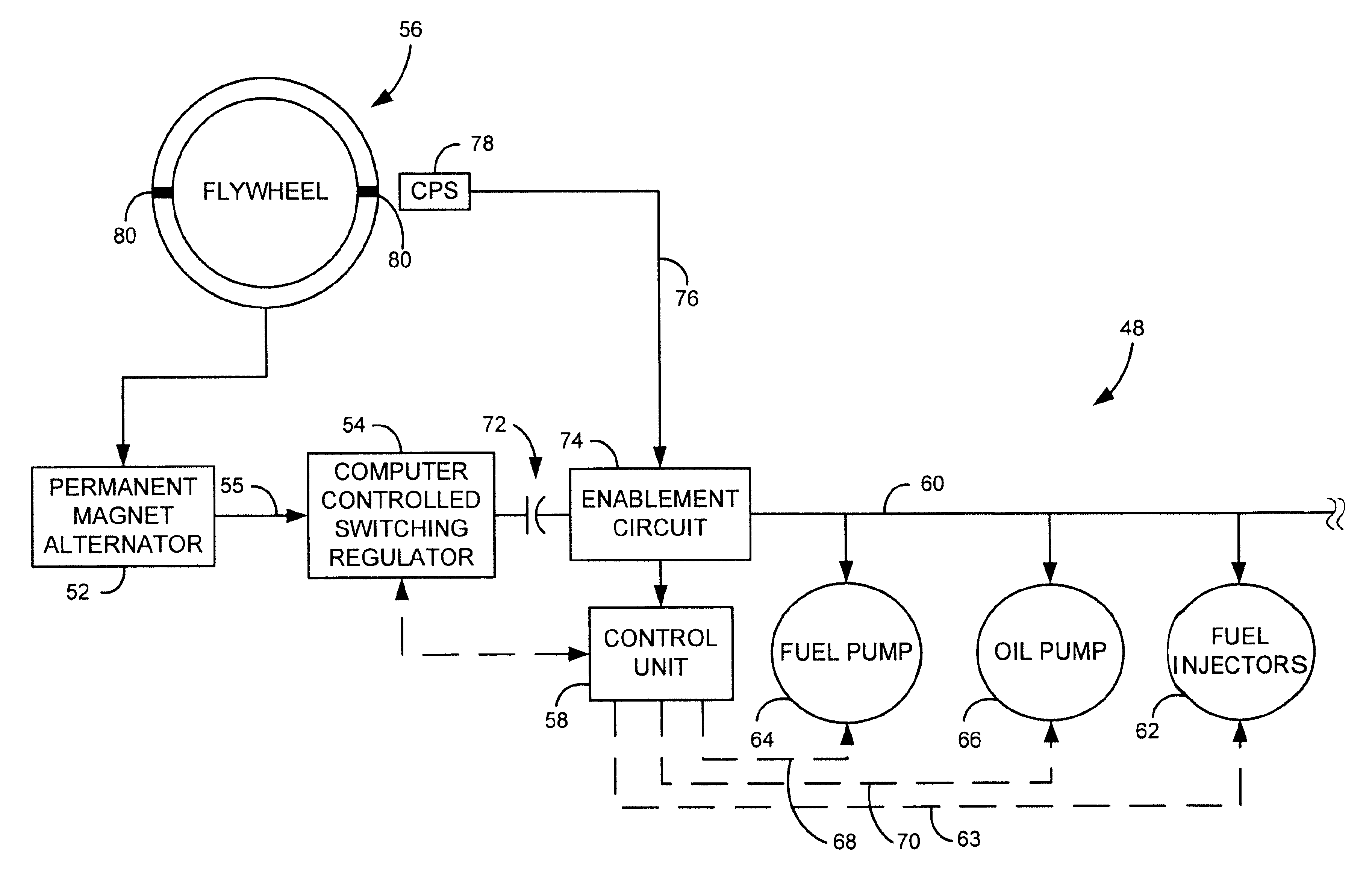
Figure 1 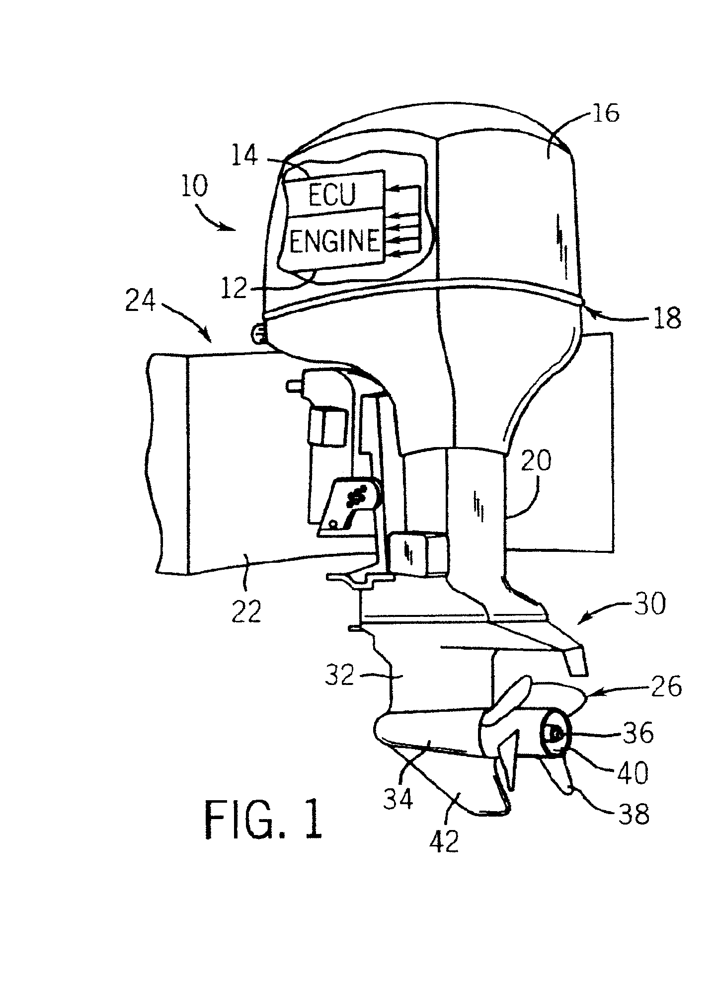
Figure 2 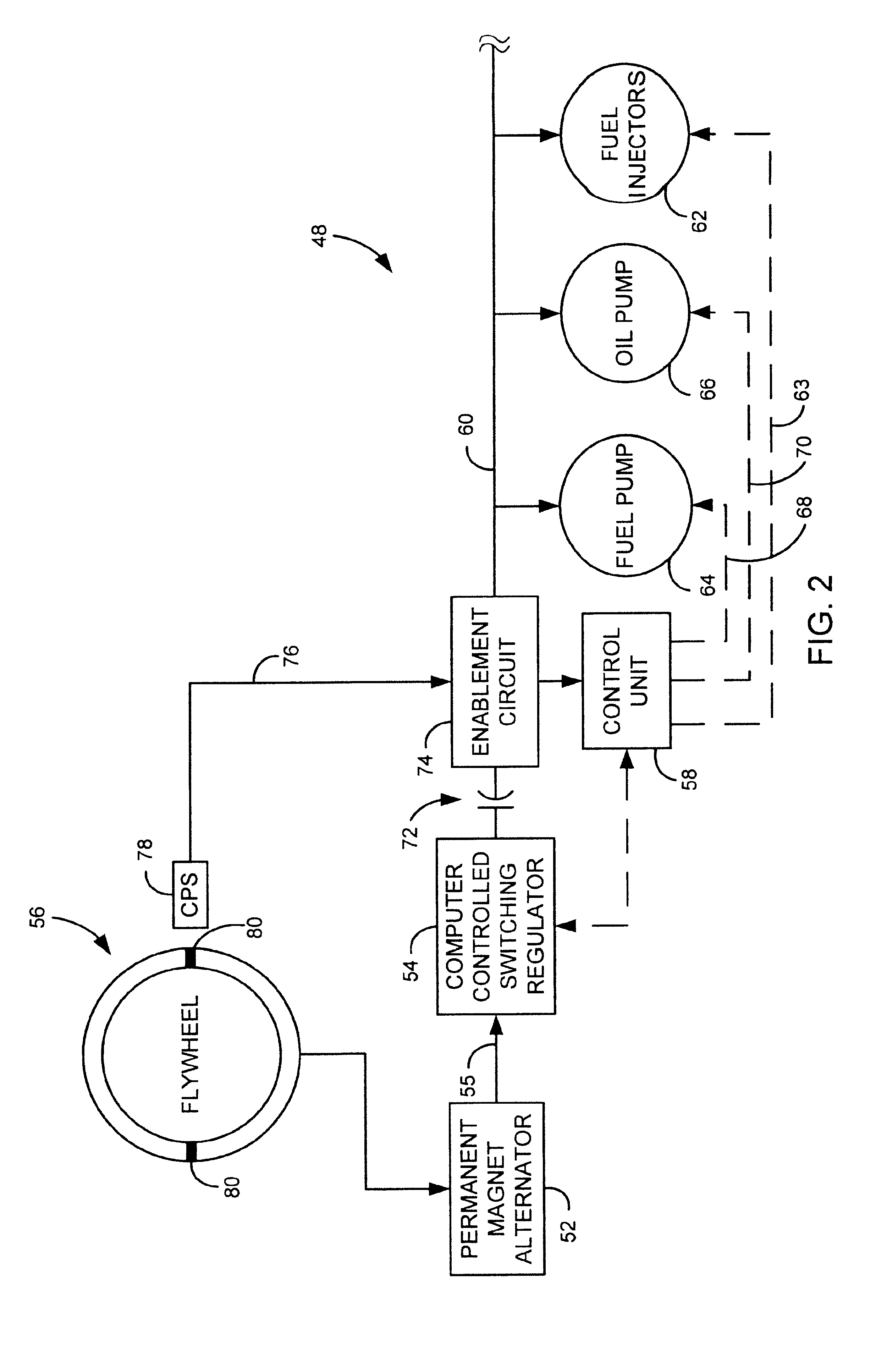
Figure 3
Abstract
Description
BACKGROUND OF INVENTION
[0001] The present invention relates generally to internal combustion engines and, more particularly, to an engine control unit enablement system that stores electrical energy upon engine shut-down such that at a subsequent engine start-up the engine control unit may be powered nearly instantaneously.
[0002] Rope-start, two-stroke engines are used in a variety of applications including outboard marine engines, snowmobiles, PWCs, ATVs, motorcycles, and lawn and garden equipment. These engines are started by manually actuating a starter mechanism that drives the engine to rotate. Engine rotation initiates a firing sequence by enabling the supply of electrical power to the engine's fuel injection and / or ignition systems that are dynamically controlled by an engine control unit. The most common manually actuated starter mechanism includes a rope that is wound around a spool coupled to the engine's flywheel either directly or via one or more gears. The rope unwinds fr...
Examples
Embodiment Construction
[0021]The present invention relates generally to internal combustion engines, and preferably, to those whose operations are controlled by an engine management module (EMM), or more generally, by a control unit or ECU. FIG. 1 shows an outboard motor 10 having an engine 12 controlled by a control unit 14 mounted directly to the engine under engine cover 16. Engine 12 is housed generally in a powerhead 18 and is supported on a mid-section 20 configured for mounting on a transom 22 of a boat 24 or other water-going vessel in a known conventional manner. Engine 12 is coupled to transmit power to a propeller 26 to develop thrust and propel boat or other watercraft 24 in a desired direction. The motor 10 includes a lower unit 30 having a gear case 32 that includes a bullet or torpedo section 34 formed therein and housing a propeller shaft 36 that extends rearwardly therefrom. Propeller 26 is driven by propeller shaft 36 and includes a number of fins 38 extending outwardly from a central hu...