
Angular position sensor
a technology of angular position and sensor, applied in the field of magnetic sensors, can solve problems such as acceptable rotation error of devices, and achieve the effect of significant accuracy and accurate detection
Patent Information
- Authority / Receiving Office
- US · United States
- Patent Type
- Patents(United States)
- Current Assignee / Owner
- Publication Date
- 2005-11-01
- Estimated Expiration
- Not applicable · inactive patent
Smart Images
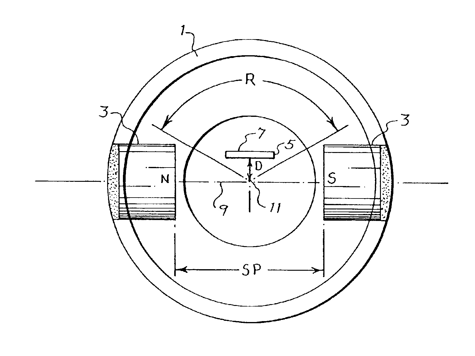
Figure 1 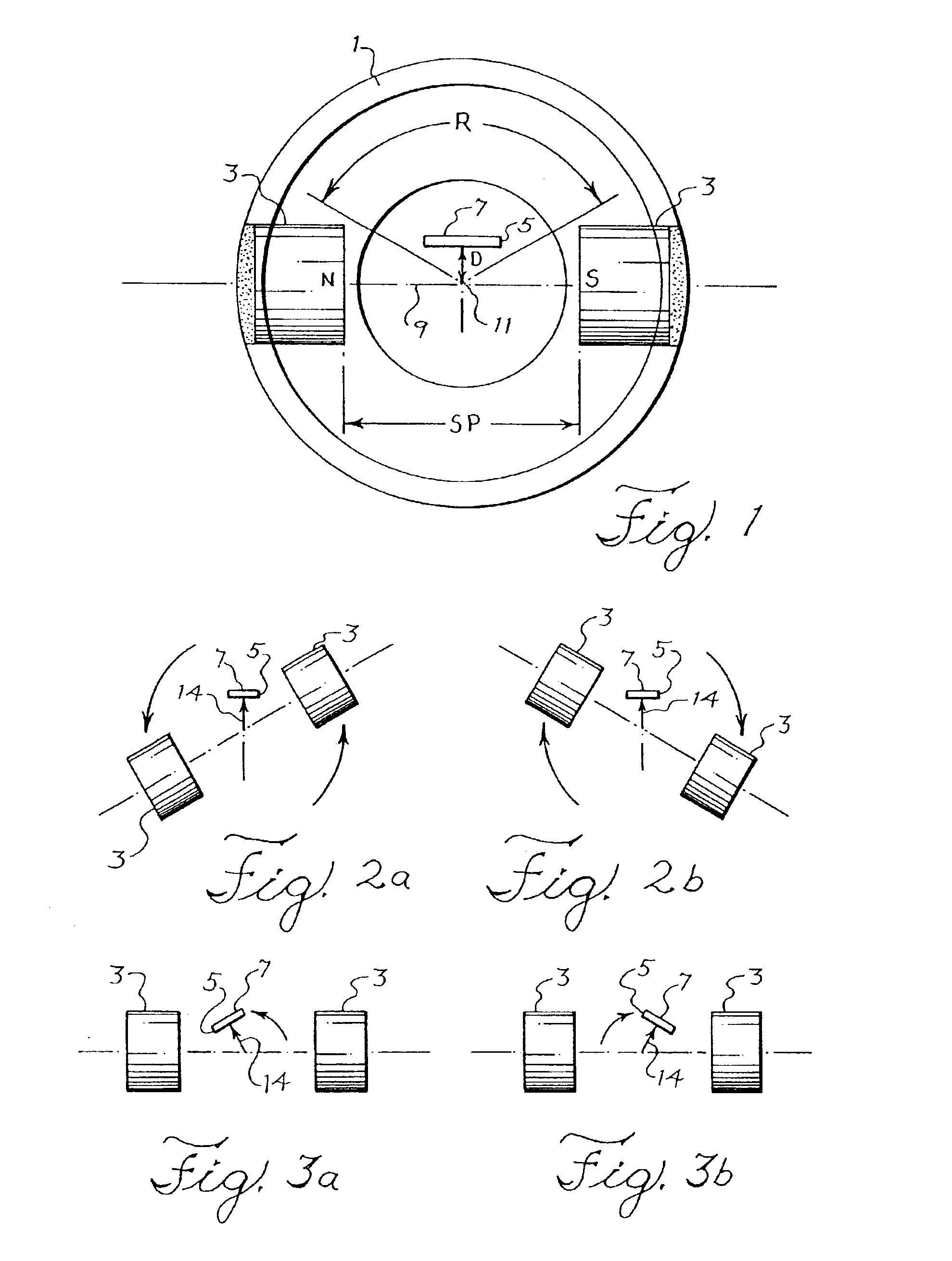
Figure 2 
Figure 3
Abstract
Description
BACKGROUND OF THE INVENTION
[0001] 1. Technical Field of the Invention
[0002] The invention concerns a magnetic sensor that is used to detect the rotation of an operating component of a machine. More particularly, the invention concerns the use of magnets and an associated magnetosensitive device such as a hall-effect sensor which detects the operational rotation of a throttle, for example as is used to control the engine of a motorcycle or automobile.
[0003] 2. Description of Related Art
[0004] It is known that two opposing magnets may be affixed to a cylinder so that the magnets rotate in opposed orientation as the cylinder rotates on its axis. It is also known that the moving magnetic field of the magnets can be detected by a stationary magnetosensitive detector such as a hall-effect sensor that is disposed within the rotating cylinder and between the opposed magnets. The sensor detects the changing angle of magnetic flux at its upper flux sensitive face as the magnets rotate, and genera...
Examples
Embodiment Construction
[0028]FIG. 1 is a schematic diagram of an improved angular position sensor. As shown in FIG. 1, a cylinder 1 contains a pair of opposed magnets 3 and an offset magnetosensitive detector or flux sensor 5, for example a hall-effect flux sensor or magnetoresistor, which generates electrical signals that correspond to the intensity of magnetic flux detected normal to the top sensing face 7 of the device. Magnetosensitive devices having a different detecting orientation would have correspondingly different offset orientations.
[0029]The magnets 3 are affixed to the cylinder 1 with their opposite north (N) and south (S) poles facing one another. An imaginary line 9 of geometric and magnetic symmetry passes through the axis of rotation 11 of the cylinder 1 and connects the faces of the magnets. The line 9 lies on the diameter of a circular cross-section of the cylinder 1. The disposition of the magnets is therefore symmetrical with respect to the line 9 and axis 11 of rotation of the cylind...