
Digital cueing receiver
Patent Information
- Authority / Receiving Office
- US · United States
- Current Assignee / Owner
- Publication Date
- 2006-11-14
Smart Images
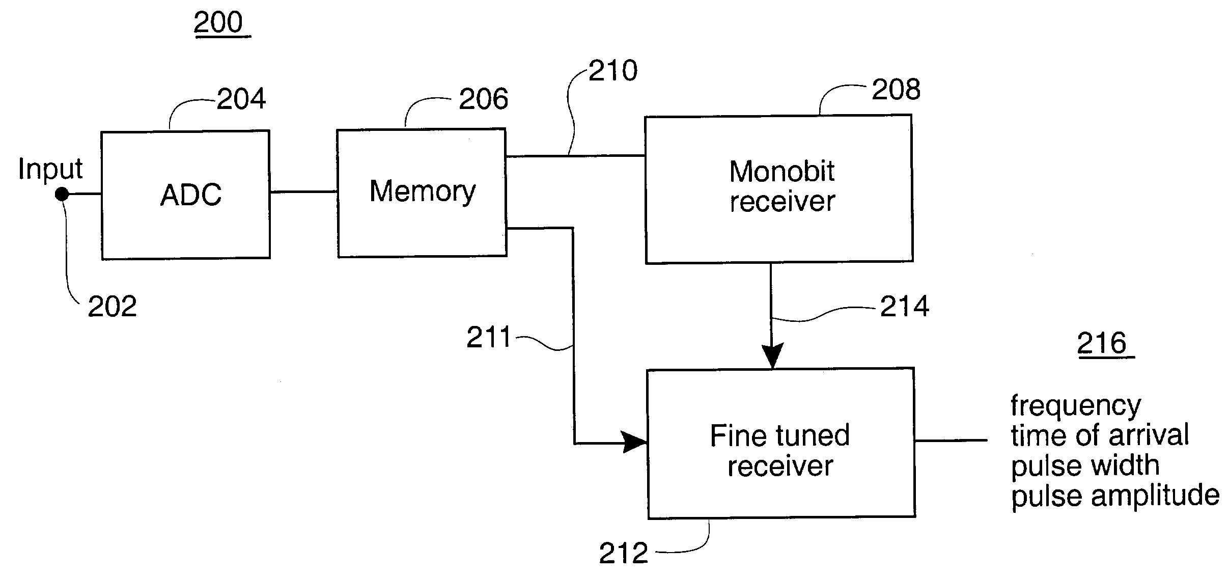
Figure 1 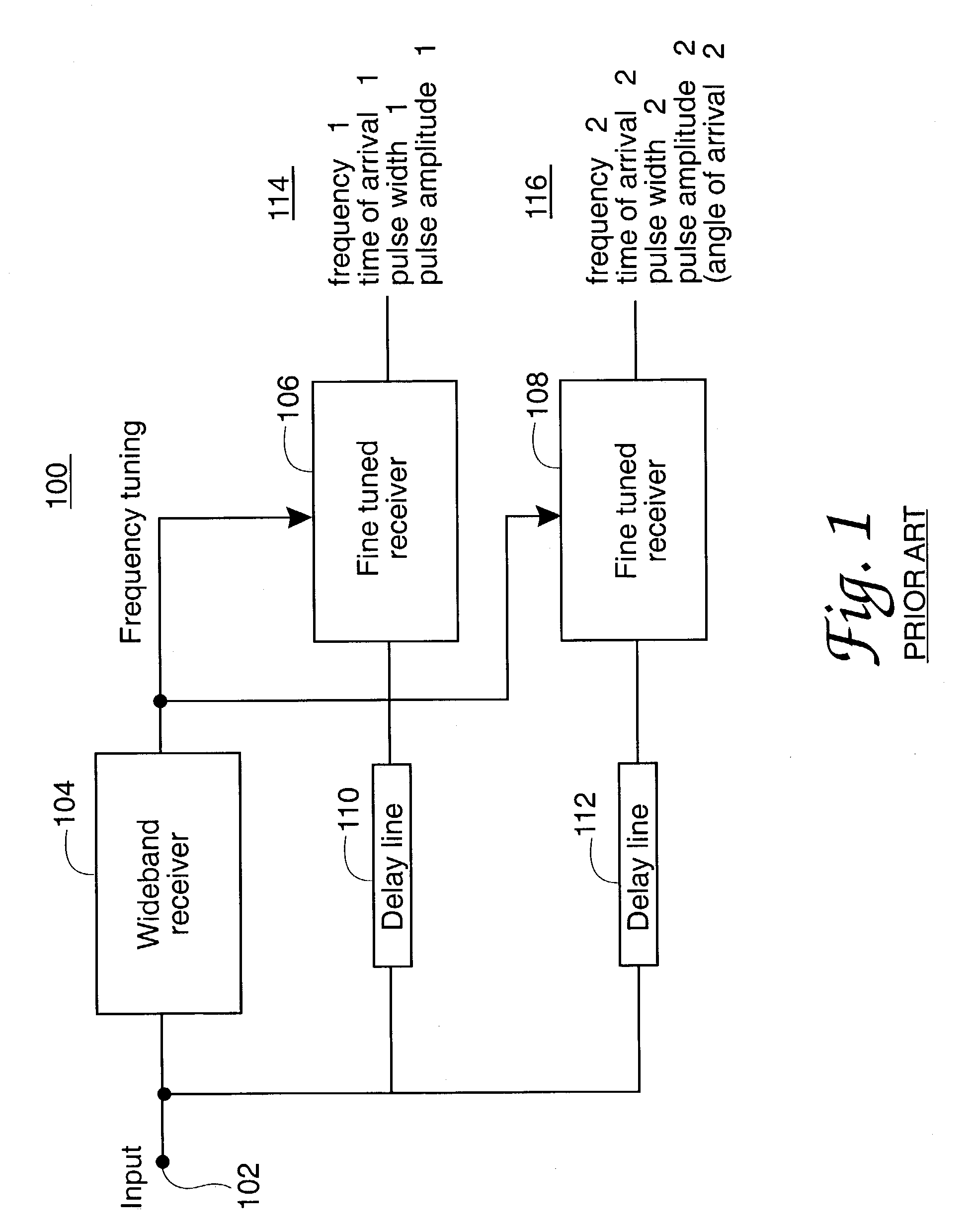
Figure 2 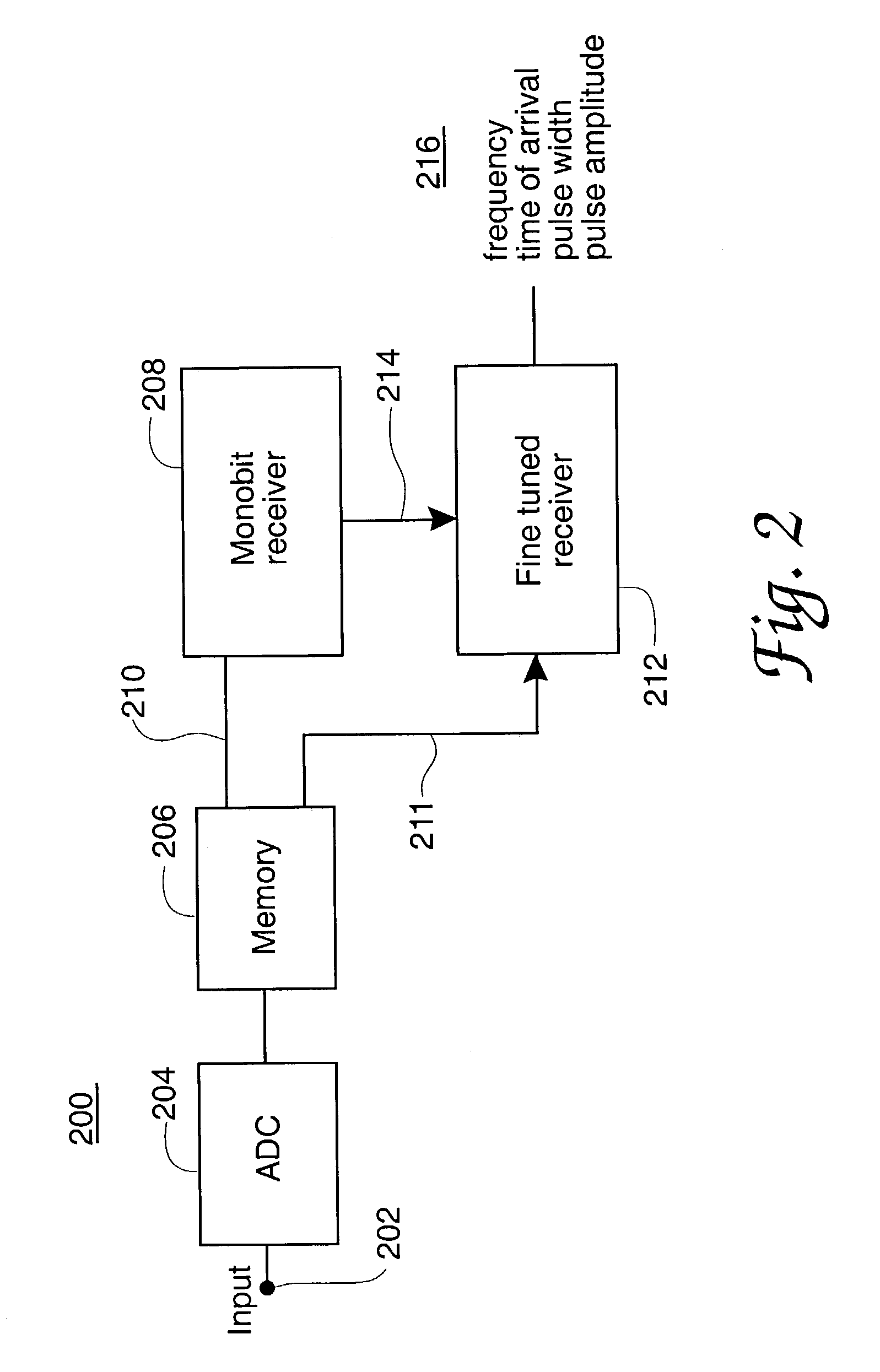
Figure 3
Abstract
Description
RIGHTS OF THE GOVERNMENT
[0001] The invention described herein may be manufactured and used by or for the Government of the United States for all governmental purposes without the payment of any royalty.BACKGROUND OF THE INVENTION
[0002] Cueing radio receiver receivers are used to control the frequency selection in a second radio receiver in a number of electronic applications, including military electronic warfare systems. As shown in certain of the prior patents identified in connection with the present document, these uses also include signal recorders, signal analyzers and signal processing systems of plural types. Heretofore such cueing receivers have been realized in analog signal processing form and have thus encountered implementation difficulty, size, cost and complexity sufficient to suggest sparing use of such receivers. Additional background information regarding the cueing receiver and its applications may be found in a textbook authored by one of the inventors named in the...
Examples
Embodiment Construction
[0022]FIG. 1 in the drawings shows the general principles of a present-day analog cueing receiver system 100. In the FIG. 1 apparatus input signals located within a wide band portion of the electromagnetic spectrum, usually at microwave frequencies, arrive at the node 102 from a receiving antenna and are applied to the input port of a wideband receiver circuit 104 and also propagated toward two narrowband receiver circuits 106 and 108. The input signals at 102 are first processed by the receiver circuit 104, which may be of the channelized receiver type or be another type of receiver having a wide instantaneous bandwidth capability and the ability to identify the frequency of each of multiple input signal component.
[0023]The frequency information determined by the wideband receiver circuit 104 is used to tune one or more fine-tuned receiver circuits such as those shown at 106 and 108 in order to obtain more detailed additional information about the individual input signal(s) receive...