
Turbine vane with endwall cooling
a turbine vane and endwall cooling technology, which is applied in the direction of engine fuction, stators, machines/engines, etc., can solve the problems of limited turbine inlet temperature, hot flow ingestion into a section of the turbine, and limited material properties of the turbine parts
Patent Information
- Authority / Receiving Office
- US · United States
- Patent Type
- Patents(United States)
- Current Assignee / Owner
- Publication Date
- 2012-02-21
- Estimated Expiration
- Not applicable · inactive patent
Smart Images
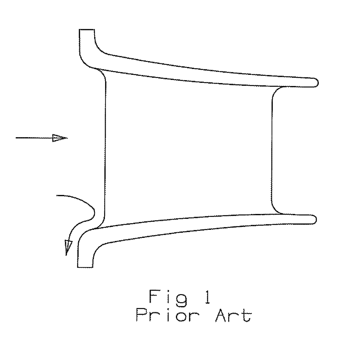
Figure 1 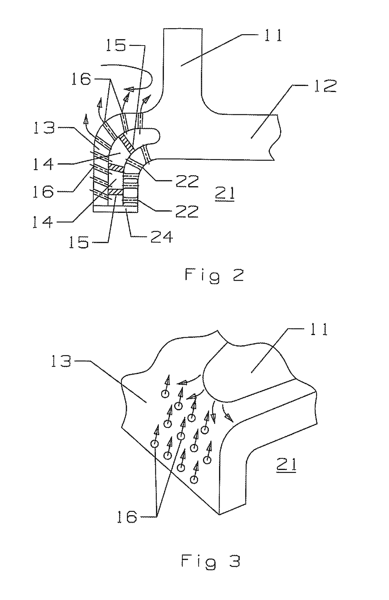
Figure 2
Abstract
Description
GOVERNMENT LICENSE RIGHTS
[0001] None.CROSS-REFERENCE TO RELATED APPLICATIONS
[0002] None.BACKGROUND OF THE INVENTION
[0003] 1. Field of the Invention
[0004] The present invention relates generally to a gas turbine engine, and more specifically to a turbine vane.
[0005] 2. Description of the Related Art including information disclosed under 37 CFR 1.97 and 1.98
[0006] A gas turbine engine, such as an industrial gas turbine (IGT) engine, includes a turbine with multiple rows or stages or stator vanes that guide a high temperature gas flow through adjacent rotors of rotor blades to produce mechanical power and drive a bypass fan, in the case of an aero engine, or an electric generator, in the case of an IGT. In both cases, the turbine is also used to drive the compressor.
[0007] It is well known that the efficiency of the engine can be increased by passing a higher temperature gas flow into the turbine. However, the turbine inlet temperature is limited to the material properties of the turbine part...
Examples
Embodiment Construction
[0019]The present invention is a turbine stator vane for an industrial gas turbine engine. However, the present invention is also usable in an aero engine stator vane as well FIG. 2 shows a cross section side view of a stator vane leading edge endwall with the cooling circuit of the present invention. The stator vane includes a leading edge 11 that extends from an outer endwall (not shown) to an inner endwall 12. The inner endwall 12 extends beyond the leading edge and curves downward to form the flow path for a hot gas flow that is passing through the turbine. This region is referred to as the endwall edge 13.
[0020]The endwall edge 13 includes an outer surface and an inner surface that forms a cooling air supply cavity 21. The endwall edge 13 includes a compartment slot or channel 14 that is machined from the endwall edge 13. A number of compartment divider ribs 15 separate a number of compartments 14 from each other. The inner surface includes a number of impingement holes 22 that...