Liquid crystal injection method and liquid crystal utensil thereof

A liquid crystal and liquid crystal material technology, applied in nonlinear optics, instruments, optics, etc., can solve the problems of liquid crystal material overflow, liquid crystal material quality degradation, low surface tension, etc., to avoid aging, save usage, and reduce overflow Effect

Active Publication Date: 2008-12-24
AU OPTRONICS CORP
View PDF6 Cites 0 Cited by
  • Summary
  • Abstract
  • Description
  • Claims
  • Application Information

AI Technical Summary

Problems solved by technology

In the prior art, the residual liquid crystal material will be used repeatedly, so after repeated steps, there will be a problem of material aging, resulting in a decline in the quality of the liquid crystal material
[0004] Additionally, in reference to Figure 1d As shown, since the liquid crystal material 14 has a relatively low surface tension in the recessed portion 12, it is easy to overflow the liquid crystal material when touching the panel 2

Method used


Image

  • Liquid crystal injection method and liquid crystal utensil thereof
  • Liquid crystal injection method and liquid crystal utensil thereof
  • Liquid crystal injection method and liquid crystal utensil thereof

Examples


Embodiment Construction

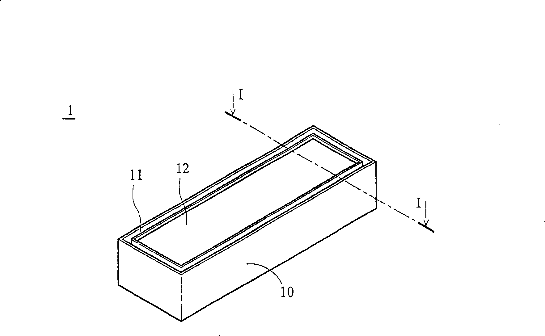
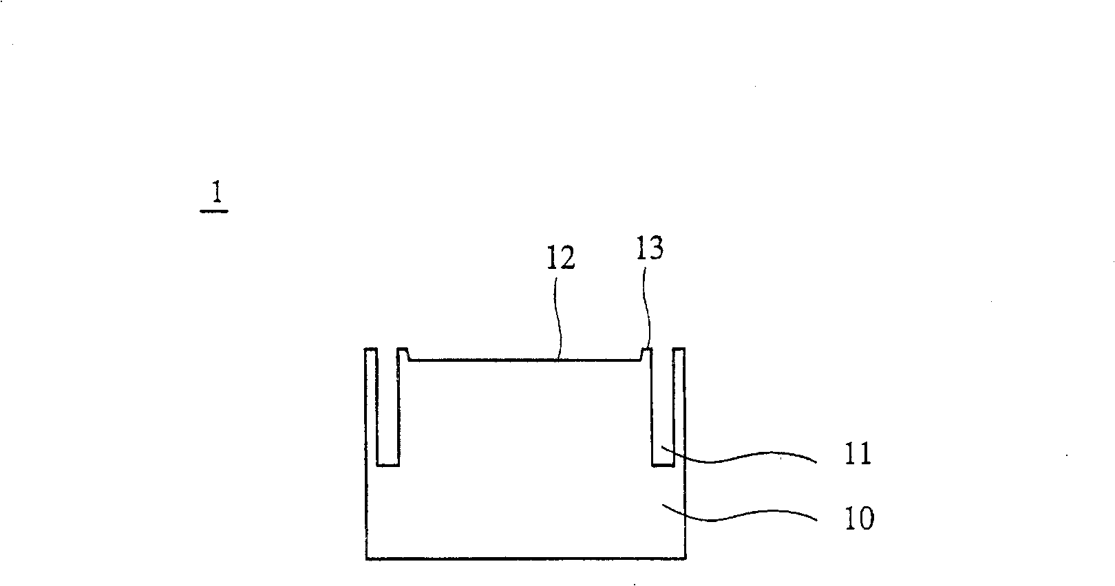
[0053] refer to Figure 2a , which shows the liquid crystal cell 100 of the first embodiment of the present invention, the liquid crystal cell 100 includes a body 101, the body 101 includes a first side surface 110, a second side surface 120, a third side surface 130, a fourth side surface The side surface 140 , a bearing surface 150 and a bottom surface 160 . The supporting surface 150 is opposite to the bottom surface 160 . The first side surface 110 , the second side surface 120 , the third side surface 130 and the fourth side surface 140 are adjacent to the supporting surface 150 and the bottom surface 160 .

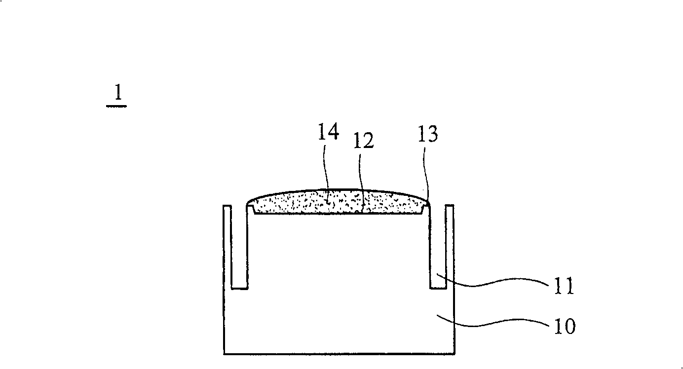
[0054] refer to Figure 2b , when performing the liquid crystal injection step, firstly, the liquid crystal material 14 will drop on the bearing surface 150 . The bearing surface is defined here. In the embodiments of the present invention and the claims, the definition of the bearing surface is: when the liquid crystal material is dripped, the entire surface that...


PUM


Abstract

The invention relates to a liquid crystal injection method and liquid crystal plate. The liquid crystal plate includes a main-body, the main-body comprising a bearing surface, a bottom surface and four side surfaces, the bearing surface adjacent to the lateral surfaces, the bottom surface corresponding to the bearing surface, in which the bearing surface is formed by a whole plane. The liquid crystal injection method and liquid crystal plate of this invention can reduce the overflow of liquid crystal material, saving liquid crystal usage volume, and directly avoiding the liquid crystal material aging problem.

Description

technical field [0001] The invention relates to a liquid crystal injection method and its liquid crystal container, in particular to a liquid crystal injection method capable of saving liquid crystal material and the liquid crystal container. Background technique [0002] refer to Figure 1a As shown, the conventional liquid crystal cell 1 includes a body 10 , a groove 11 and a recess 12 . refer to Figure 1b shown, which shows the Figure 1a I-I sectional view in , wherein the recessed portion 12 includes an edge 13 . refer to Figure 1c As shown, when performing the liquid crystal injection step, firstly, the liquid crystal material 14 will drop into the recessed portion 12 . Next, refer to Figure 1d As shown, the panel 2 touches the edge 13, and the liquid crystal material 14 is then sucked into the panel 2 from the recess 12 by capillary phenomenon. [0003] In the above-mentioned liquid crystal injection step, since only a small amount of liquid crystal material n...

Claims


Application Information

Patent Timeline
Patent Type & Authority Patents(China)
IPC IPC(8): G02F1/1341
Inventor 李奕均赖志明
Owner AU OPTRONICS CORP
Why Eureka
Try Eureka