Centralized pressure supplying method of hydraulic stations

A technology of hydraulic station and pressure oil pipe, which is applied in the direction of fluid pressure actuation device, fluid pressure actuation system components, servo motor components, etc., which can solve the problems of low effective utilization rate of hydraulic station and waste of electric energy, etc., and improve the effective utilization rate , reduce the waste of electric energy, and meet the needs of machine tool work

Active Publication Date: 2015-10-21
重庆市博平液压机械有限公司
View PDF10 Cites 2 Cited by
  • Summary
  • Abstract
  • Description
  • Claims
  • Application Information

AI Technical Summary

Problems solved by technology

[0008] The technical problem to be solved by the present invention is to provide a centralized pressure supply method for hydraulic stations for large and medium-sized machinery processing plants with multiple machine tools containing hydraulic stations. The effective utilization rate of hydraulic stations is low and the waste of electric energy is serious.

Method used


Image

  • Centralized pressure supplying method of hydraulic stations
  • Centralized pressure supplying method of hydraulic stations
  • Centralized pressure supplying method of hydraulic stations

Examples


Embodiment 1

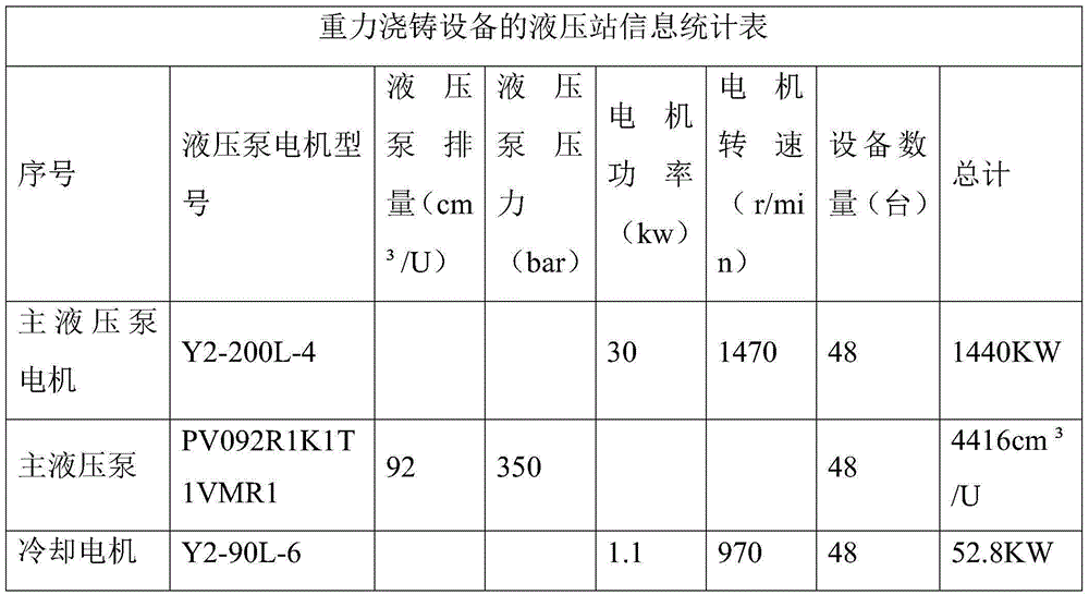
[0027] A machinery processing factory has 3 gravity casting equipment lines arranged side by side, each production line has 16 gravity casting equipment, and each gravity casting equipment has an independent hydraulic station. The hydraulic station parameters of the gravity casting equipment in this factory are as follows :

[0028]

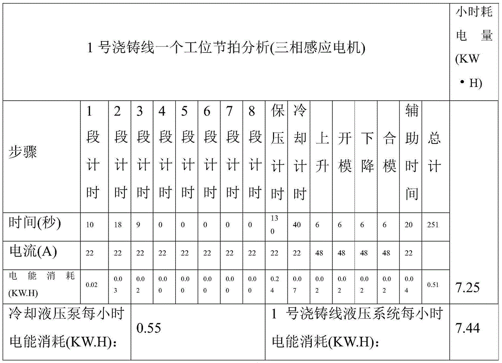
[0029] Among the 3 gravity casting equipment lines arranged side by side in this factory, the power consumption of No. 1 casting line is as shown in Table 1:

[0030]

[0031] Table 1

[0032] According to the data analysis in Table 1, the current power consumption of the hydraulic system of this equipment is about 11.66 degrees per hour.

[0033] The annual power consumption of the hydraulic systems of the 48 equipment of the 3 gravity casting equipment lines arranged side by side in this factory is shown in Table 2:

[0034]

[0035] Table 2

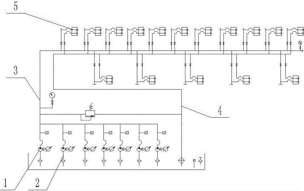
[0036] The solution of the present invention: the centralized pressure supply method of th...

Embodiment 2

[0070] The difference between embodiment two and embodiment one is: take 30% of the maximum flow accumulation value, that is, 1325cm 3 / U and 30% of the accumulated maximum pressure, namely 5040bar, are the rated flow and rated pressure of the new hydraulic station respectively.

Embodiment 3

[0072] The difference between embodiment three and embodiment two is: take 25% of the maximum flow accumulation value, that is, 1104cm 3 / U and 25% of the accumulated value of the maximum pressure, namely 4200bar, are the rated flow and rated pressure of the new hydraulic station respectively.


PUM


Abstract

The invention provides a centralized pressure supplying method of hydraulic stations to overcome the defects that in traditional large and medium machining factories, the effective utilization rate of hydraulic stations is low, and waste of electric energy is serious. The method comprises the following steps that A, when machine tools including the hydraulic stations work with the full load, the needed maximum flow and the needed maximum pressure are counted, and the accumulated values of the maximum flow and the maximum pressure are calculated respectively; B, 20%-30% of the maximum flow accumulated value and 20%-30% of the maximum pressure accumulated value are taken as the rated flow value and the rated pressure value of a new hydraulic station; C, a pressure oil pipe and an oil return pipe are connected to the new hydraulic station, and terminal valve sets of all the machine tools are connected to the pressure oil pipe and the oil return pipe in parallel; and D, pressure is supplied to the pressure oil pipe through the new hydraulic station, the terminal valve set, corresponding to the machine tool, on the pressure oil pipe is opened according to the specific working machine tool, hydraulic branches corresponding to the machine tools need pressure maintaining by adjusting the terminal valve sets, and the terminal valve sets corresponding to the machine tools are closed when the machine tools do not work.

Description

technical field [0001] The invention belongs to the field of machine tool hydraulic systems, and in particular relates to a centralized pressure supply method of a hydraulic station. Background technique [0002] At present, most of the tooling and fixtures on CNC (that is, numerically controlled machine tools) and the tooling and molds on gravity casting machines are driven by small hydraulic stations. Usually CNC is used in the manufacture of parts for automobiles and motorcycles, as well as the manufacture of hardware and electrical machinery, and the gravity casting machine is used for casting parts of large industrial equipment. [0003] Usually, when machinery factories purchase CNC equipment, they will purchase more than one CNC equipment. According to incomplete statistics, 80% of machinery factories in Chongqing have CNCs with hydraulic stations, and there are no less than 10 machinery factories with more than 1,000 CNCs with hydraulic stations. Since each machine ...

Claims


Application Information

Patent Timeline
Patent Type & Authority Applications(China)
IPC IPC(8): F15B13/02F15B21/08F15B21/02
CPCF15B13/02F15B21/02F15B21/08
Inventor 高戴明
Owner 重庆市博平液压机械有限公司
Why Eureka
Try Eureka