Supercharge Your Innovation With Domain-Expert AI Agents!

A device for containing a die of a calibrating workpiece and a pressing mechanism thereof

A technology of presses and molds, applied in the field of mold devices, can solve problems such as failure to modularize, complex workpieces, and undiscovered problems, and achieve the effect of reducing the time for changes

Inactive Publication Date: 2009-03-04
ALVIER PM TECH
View PDF8 Cites 0 Cited by
  • Summary
  • Abstract
  • Description
  • Claims
  • Application Information

AI Technical Summary

Problems solved by technology

In practice, however, these devices are not sufficiently modular and adaptable for complex workpieces
[0003] In the invention patent literature, no device has been found to accommodate the mold for correcting the workpiece. The utility model patent DE 90 12 752.8 in 1991 discloses an adapter for molds, in which the mold is used to compress metal powder to manufacture workpieces

Method used


Image

  • A device for containing a die of a calibrating workpiece and a pressing mechanism thereof
  • A device for containing a die of a calibrating workpiece and a pressing mechanism thereof
  • A device for containing a die of a calibrating workpiece and a pressing mechanism thereof

Examples


Embodiment Construction

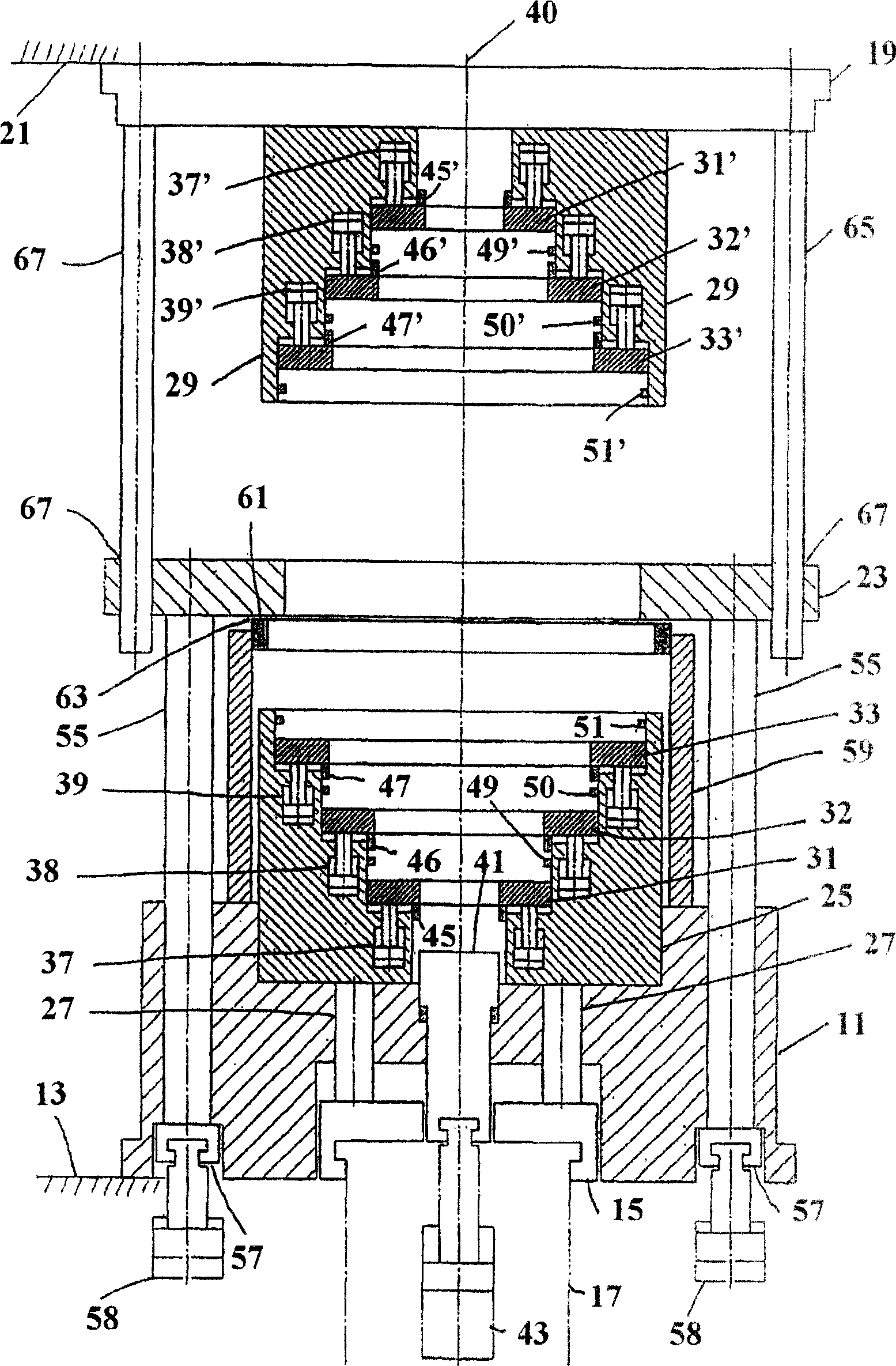
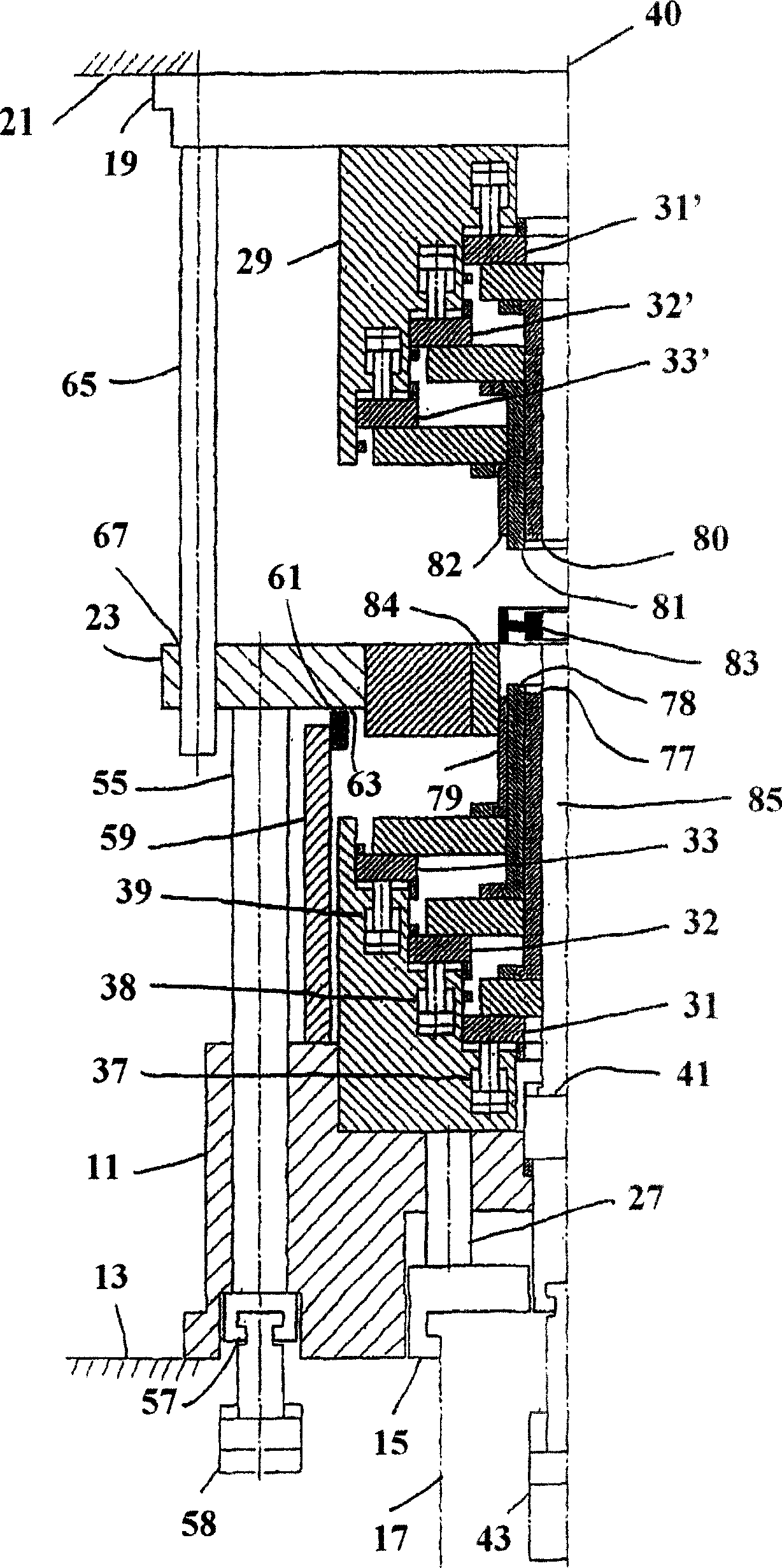
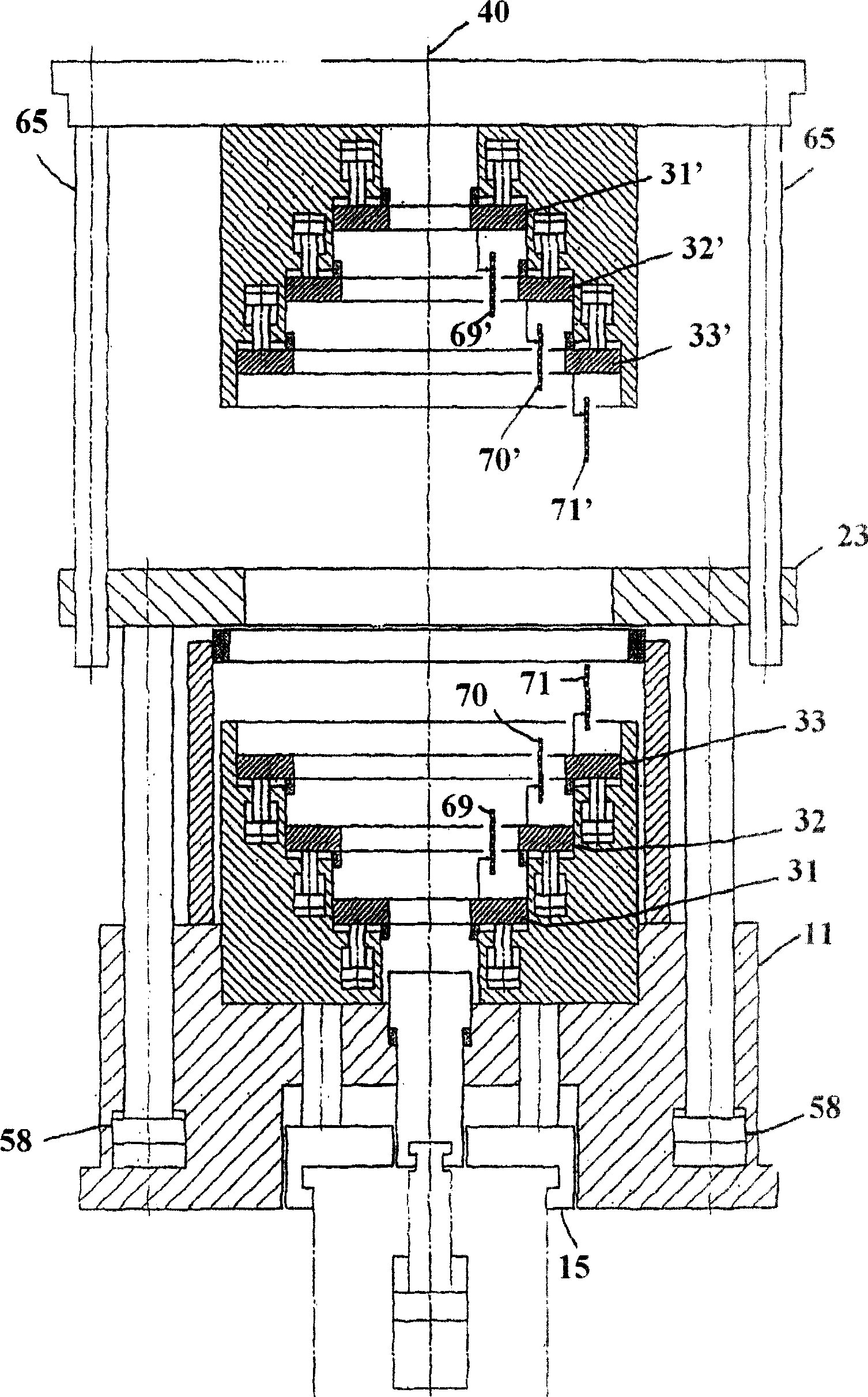
[0018] like figure 1 and figure 2 As shown, the device comprises a base plate 11, such as a square shape, for mounting to a platform 13 of a press, a lower connecting plate 15 fixed to the extrusion piston or lower ram 17 of the press, and an upper connecting plate 19 fixed to the Press head 21 on. The mold support plate 23 is located in the space between the base plate 11 and the upper connection plate 19 .

[0019] The lower mold accommodating unit 25 is connected to four rods 27 to be connected to the connecting plate 15 . The upper mold accommodating unit 29 is connected to the upper connection plate 90 . The lower mold receiving unit 25 comprises three mold supports 31 , 32 , 33 which can be moved back and forth individually or together by actuating mechanisms parallel to the axis 40 , such as hydraulic cylinders 37 , 38 , 39 . In the embodiment shown, the actuating mechanisms 37, 38, 39 are integrally formed with the mold containing unit. The mold supports 31, 32, ...


PUM


Abstract

The device serves to receive a tool for calibrating of workpieces (83), preferably workpieces manufactured by a powder metallurgical process. On the example shown the tool comprises the lower stamps (77, 78, 79) and the upper stamps (80, 81, 82) located on tool supports (31, 32, 33; 31', 32', 33'). These stamps may be moved up and down individually or together parallel to the axis (40). Also movable up and down is the tool support (41) on which, if required, a center pin (85) is mounted. The device is particularly suitable for the calibration of complicated workpieces, such as represented for example by the workpiece (83) having the form of a body of rotation.

Description

technical field [0001] The invention relates to a device for receiving molds for correcting workpieces, especially workpieces produced by powder metallurgy. Background technique [0002] To manufacture workpieces using powder metallurgy, metal powder or pellets are first compressed in a mold. The objects obtained in this way are then sintered in a furnace. Workpieces produced in this way usually do not have the required dimensional accuracy and surface quality. In order to improve dimensional accuracy and surface quality, it is known to further work the workpiece, ie to carry out so-called corrections. For this purpose, the workpiece is placed in a mould, to which high pressure is applied, which can be of the order of 60 kN per square centimeter. In this way, the workpiece structure is compressed. In addition, surface quality and dimensional accuracy are improved. Correction is currently performed by relatively simple means. In practice, however, these devices are not ...

Claims


Application Information

Patent Timeline
Patent Type & Authority Patents(China)
IPC IPC(8): B22F3/03B30B11/02
CPCB30B11/02B22F3/03B30B11/005
Inventor H·古德P·劳赫
Owner ALVIER PM TECH
Features
  • R&D
  • Intellectual Property
  • Life Sciences
  • Materials
  • Tech Scout
  • Unparalleled Data Quality
  • Higher Quality Content
  • 60% Fewer Hallucinations
Learn More