U-shaped steel-wood composite beam as well as supporting system and construction method thereof

A technology of support system and construction method, applied in the fields of formwork/template/work frame, on-site preparation of building components, construction, etc., can solve the problems of natural environment damage, increase construction cost, affect construction quality, etc., to reduce Labor intensity, flexible use, light weight effect

Active Publication Date: 2009-10-21
BEIJING URBAN CONSTR FIFTH CONSTR GRP
View PDF6 Cites 0 Cited by
  • Summary
  • Abstract
  • Description
  • Claims
  • Application Information

AI Technical Summary

Problems solved by technology

[0004] The purpose of the present invention is to provide a U-shaped steel-wood composite beam and its support system and construction method, to solve the problems caused by excessive consumption of wood in building construction, resulting in increased construction costs, serious waste, and affecting construction quality, and at the same time solve the problems caused by The problem of the destruction of the natural environment caused by this

Method used


Image

  • U-shaped steel-wood composite beam as well as supporting system and construction method thereof
  • U-shaped steel-wood composite beam as well as supporting system and construction method thereof
  • U-shaped steel-wood composite beam as well as supporting system and construction method thereof

Examples


Embodiment 1

[0040] Embodiment one, see Figure 5 As shown, the U-shaped steel-wood composite beam support system is used for roof formwork construction, and the steps are as follows:

[0041] Step 1, use the bowl buckle frame to erect the main keel 8, the main keel can be 50×100mm square steel;

[0042] Step 2, evenly laying U-shaped steel-wood composite beams 7 on the main keel with a spacing of 300-350 mm.

[0043] Step 3, laying a bottom formwork 9 above the U-shaped steel-wood composite beam, and constructing a concrete floor 11 on the bottom formwork 9.

[0044] The length specification of the U-shaped steel-wood composite beam is 0.5m as the modulus, ranging from 2m to 4m, and different lengths are selected according to the headroom size of the room. The lap length should be greater than 500mm, and the cantilever length should not be greater than 500mm.

Embodiment 2

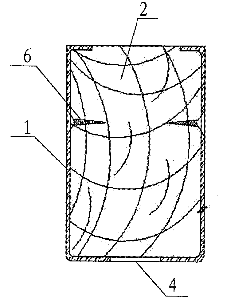
[0045] Embodiment two, see Image 6 As shown, the U-shaped steel-wood composite beam support system is used for beam formwork construction, and the steps are as follows:

[0046] Step 1, build the main keel 8 on the supporting frame 10, the main keel may be 90×90mm, and the spacing may be 600mm.

[0047] Step 2, evenly laying U-shaped steel-wood composite beams 7 on the main keel 8, and laying a bottom template 9 on the U-shaped steel-wood composite beams 7;

[0048] Step 3, tie beam reinforcement, place formwork 15 on both sides, set U-shaped steel-wood composite beam 7 on the outside of side formwork 15, and fix it with back corrugated 13 and cross-piercing bolt 14;

[0049] Step 4, pouring concrete.

Embodiment 3

[0050] Embodiment three, see Figure 7 As shown, the U-shaped steel-wood composite beam support system is used for column formwork construction, and the steps are as follows:

[0051]Step 1, support four side formworks 15, and the above-mentioned side formworks 15 can be multi-layer boards with a thickness of 15 mm. Evenly lay U-shaped steel-wood composite beams 7 outside the side formwork 15, the spacing can be 300mm, and be fixed with the side formwork 15 by screws;

[0052] Step 2, fixing with column hoop 16 on the periphery of U-shaped steel-wood composite beam 7;

[0053] Step 3, pouring concrete.

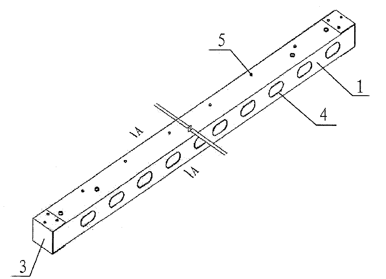
[0054] see Figure 4 As shown, when the length of the above-mentioned U-shaped steel-wood composite beam is not enough, it can be extended with a rectangular or U-shaped connecting plate 12, which has a perforation 13 on the connecting plate.


PUM


Abstract

A U-shaped steel-wood composite beam and its supporting system and construction method, which is a steel-clad wood structure, U-shaped steel plates are enclosed on the side of the square wood, and one side of the square wood, that is, the top surface of the U-shaped steel is semi-enclosed The two ends of the square wood are sealed by the head steel plate, the bottom surface of the U-shaped steel plate is distributed with large holes, and the two sides of the U-shaped steel plate are distributed with small holes, and the wood screws pass through the small holes to fix the U-shaped steel plate and the square wood. . The invention can be used as a substitute product of traditional square wood, which has high strength, light weight, low loss, can be reused many times, and changes disposable amortized materials into turnover materials, which fundamentally reduces cost consumption and can reduce waste during construction. The input of materials reduces the labor intensity of workers and improves work efficiency. Compared with the use of square timber, the use of U-shaped steel-wood beams in conventional projects can save 30%-50% of construction costs. It can be widely used in roof formwork support system, beam formwork support system, column formwork support system and other building support structures.

Description

(1) Technical field [0001] The invention relates to a component, a support system and a construction method used in building formwork construction. (2) Background technology [0002] For a long time, due to the light weight of wood, easy sawing and planing, and convenient construction, square wood has been widely used as formwork keel and back corrugated materials in construction projects, making it occupy an important position in building formwork materials for a long time. However, with the development of my country's economic construction, the annual growth of timber forest that can be harvested in my country is less than 100 million cubic meters, while the annual consumption of commercial timber is 150 million cubic meters of forest resources, and the forest resource deficit is serious. A large number of felling trees will inevitably aggravate the deterioration of the natural environment, which is not in line with the national green environmental protection policy. my c...

Claims


Application Information

Patent Timeline
Patent Type & Authority Patents(China)
IPC IPC(8): E04G11/50E04G11/48E04G13/04E04G13/02
Inventor 毛杰吴世勇李全智
Owner BEIJING URBAN CONSTR FIFTH CONSTR GRP
Why Eureka
Try Eureka