Voltage stabilizer circuit

A voltage stabilizer and circuit technology, applied in circuits, instruments, electrical components, etc., can solve the problem that the voltage stabilizer circuit is difficult to adapt to the low capacity and low ESR of the output capacitor Co.

Active Publication Date: 2010-01-20
MITSUMI ELECTRIC CO LTD
View PDF3 Cites 0 Cited by
  • Summary
  • Abstract
  • Description
  • Claims
  • Application Information

AI Technical Summary

Problems solved by technology

[0030] As mentioned above, it is difficult for existing regulator circuits to adapt to the reduction in capacity and ESR of the output capacitor Co.

Method used


Image

  • Voltage stabilizer circuit
  • Voltage stabilizer circuit
  • Voltage stabilizer circuit

Examples


Embodiment Construction

[0044] Embodiments of the present invention will be described in detail below with reference to the drawings.

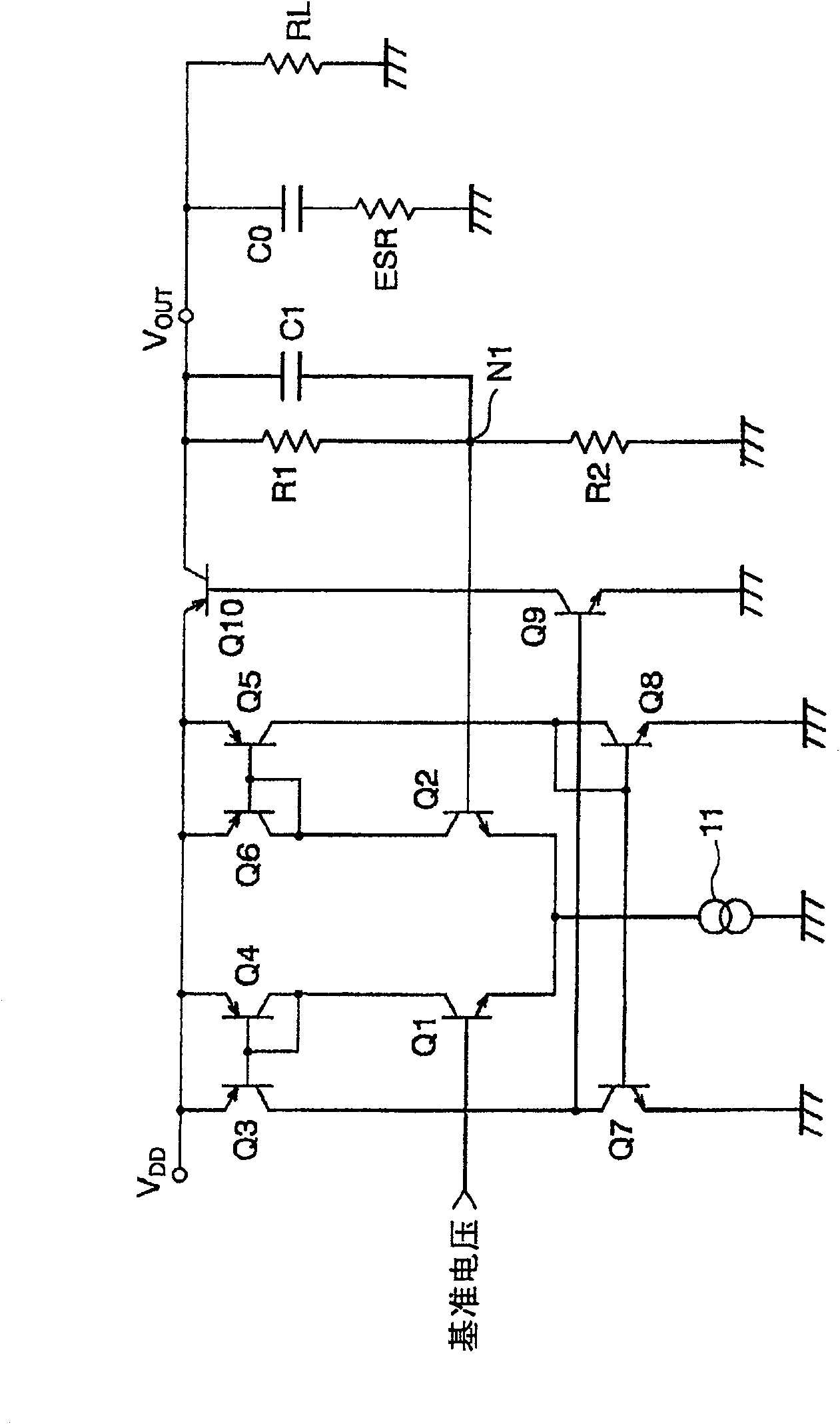
[0045] Figure 4 It is a circuit diagram of a regulator circuit (series regulator IC) of one embodiment of the present invention. This regulator circuit has basically the same configuration as a conventional regulator circuit, except that it has a phase correction circuit 40 including a second phase correction capacitor C2.

[0046] Specifically, this regulator circuit has a constant current source 11 , first to tenth transistors Q1 to Q10 , first and second resistors R1 and R2 , a first phase correction capacitor C1 and a phase correction circuit 40 . The phase correction circuit 40 is composed of third and fourth resistors R3 and R4 (for example, 5 [KΩ], 5 [KΩ]), and a second phase correction capacitor C2 (for example, 3 [pF]).

[0047] In other words, the illustrated voltage regulator circuit has a DD and the output terminal V OUT between the output transistor...


PUM


Abstract

To provide a regulator circuit capable of reducing capacitance and ESR of an output capacitor C<SB>0< / SB>at a low cost. This regulator circuit is provided with an output transistor Q10 connected between a power source terminal V<SB>DD< / SB>and an output terminal V<SB>OUT< / SB>, dividing circuits R1 and R2 dividing output voltage between the output terminal and a ground terminal to generate divided voltage from an intermediate node N1, error amplifiers Q1-Q8 and 11 generating an error signal according to a difference between a reference voltage and the divided voltage, and a control transistor Q9 controlling the output transistor according to the error signal. In the regulator circuit, a first phase correction capacitor C1 is connected between the output terminal and the intermediate node N1 of the dividing circuit, while a second phase correction capacitor C2 is connected between the output terminal and a predetermined node N2 of the error amplifiers.

Description

technical field [0001] The invention relates to a voltage stabilizer circuit, in particular to a series of voltage stabilizer ICs which must output large current. Background technique [0002] A voltage regulator circuit is a circuit that stabilizes an externally supplied power supply voltage and supplies the stabilized output voltage to an output terminal. After connecting the output capacitor to the output terminal of the voltage regulator circuit, connect the load to the output terminal of the voltage regulator circuit. In this way, the output voltage stabilized by the regulator circuit and smoothed by the output capacitor is supplied to the load. [0003] As the output capacitor Co connected to the output side of the regulator circuit, electrolytic capacitors or tantalum capacitors are generally used, but in order to meet the demand for miniaturization, the use of small-capacity ceramic capacitors is developing. [0004] However, capacitors have different ESR values ​​...

Claims


Application Information

Patent Timeline
Patent Type & Authority Patents(China)
IPC IPC(8): G05F1/56
CPCH01Q1/242H01Q1/10H01Q11/08
Inventor 山口公一
Owner MITSUMI ELECTRIC CO LTD
Why Eureka
Try Eureka